Design of a new portable tilt sensor
A new portable goniometer is designed to solve the problems of large volume and difficult reading of traditional goniometer. P2 adopts C8051 MCU. The output voltage of 0 port sensor is collected and converted by analog-to-digital conversion module of single chip microcomputer. The converted digital quantity is first processed by the average filter, then converted into Angle, and finally the Angle measurement value is output by the liquid crystal display. At the same time, RS-232 communication module is also designed. It is used to communicate with the host. The system adopts modular design idea, has the characteristics of light weight, small volume, battery power supply, easy to use and so on. The results show that: 0-90. The minimum resolution of the system is 0. 1. The sensitivity is 0. 02 V /°, with good repeatability and linearity.
0 Introduction
Inclination sensors are used to measure the inclination of instruments relative to the horizontal plane, and play an important role in aviation, solar 2J, automatic level j, military j, high-precision scientific equipment and so on. Traditional tilt sensor plays an important role in horizontal, vertical and Angle measurement because of its strong reliability and high precision, and has been widely used as a supporting instrument in many professional fields. However, in the relatively harsh environmental conditions and the state of no mains power supply, this sensor product can not be measured. Therefore, it is an urgent problem to study tilt sensor products that adapt to harsh environment, small body size, light weight, battery powered, easy to use and flexible. The author has designed an inclination measurement system based on c8051f310 single chip computer. The experimental results show that the minimum resolution of the tilt sensor is 0. 1. Its repeatability and linearity are reasonable, and it can be applied to the level and Angle measurement system of various high-precision instruments, and has very high application value.
1 Circuit system scheme
Angle sensor sca60c sensor output voltage signal and Angle normal correlation, through Analog (Analog to digital, hereinafter referred to as :a /D) conversion to convert it into digital signal, and the digital signal is transmitted to the microprocessor C805 1F3 10 for filtering, limiting, Angle processing. Make it become the real-time signal of the corresponding Angle, and display it through the display module to realize the man-machine interface. In addition, the RS-232 signal communication module is configured. The system transmits data through the RS-232 signal communication module to realize the communication with the host computer. The circuit system design adopts the modular design method, and the system structure is shown in Figure 1. After analysis, the inclination sensor is divided into the following six main modules: sensor sensor module, power module, A/D conversion module, microprocessor module, display module and RS-232 signal transmission module.
1.1 Sensor Sensor module
SC A60C is a single axis tilt sensor chip with high resolution, low noise, good stability and strong impact resistance, which is launched by VTI Technology company of Finland. The chip, which can be used to measure whether an object is in a horizontal, vertical position or at an Angle to the horizontal, is actually an accelerometer with an internal sensor, measurement circuit, gain amplification and filtering module, which converts it into a tilt Angle by measuring the gravity of the Earth in the measured direction. Convert the Angle to analog output with formula (1) :

In formula (1), is the output voltage of the Angle sensing element; Is the input Angle; Is the output voltage of the module in the horizontal position (output value is usually 2). 5 V); V is the sensitivity of the module (its sensitivity is 2v per acceleration of gravity). For better accuracy, use the actual output value instead of the usual value. The sensor has high sensitivity, and the conductivity signal generated by its tilt has a good linear correlation with the actual Angle in a small Angle range, which can be used to achieve accurate Angle measurement. The sensor is not sensitive to temperature changes, so temperature changes have little effect on measurement accuracy.
1.2 Power Module
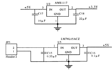
In order to provide + 5v voltage to the tilt sensor SCA 60C and the communication conversion chip MA X 232 cep in the circuit, the author uses the lm78i ~ 5A CZ stabilization chip. Through the chip can provide a stable + 5V voltage for the system, the power supply is 9V dry battery. + 3 for C805 1F3 10 single chip microcomputer. At 3V voltage, the author uses the ms1117 core chip, which can provide stable + 3 power supply for the microcontroller. 3v voltage.

Figure 2 Power module
1.3 Microprocessor module
This circuit uses MCU C8051f310 as the core of the main module unit of the microprocessor. c805 1f310 MCU is widely used, there are more source code to learn, reduce the workload, shorten the development time. c805 1f310 single chip microcomputer has 8 1024 bytes of program memory, which provides a large capacity of program memory, the input and output interface is convenient and flexible, and is favored by the majority of industrial control designers.
4 A/D conversion module
After the analog signal is selected, analog-to-digital conversion must be carried out to convert the analog signal into a digital signal that the microprocessor can recognize. The analog signal of the system is a voltage signal, and after analog-to-digital conversion, the voltage value corresponding to each Angle is converted into a unique binary digital signal, which is the signal that the microprocessor can recognize and process.
The C805 1F310 MCU Analog to D digital Converter (Adc) integrates two 25-channel analog multiplexers and a 10-bit sequential approximation Adc that samples 200,000 times per second. Dc can operate in either single-ended or differential mode, with the analog multiplexer selecting positive and negative inputs from DC P1.0 to P3. 4 and any of G, N, and D can be used as negative inputs, P1.0 to P3. 4. Either of the on-chip temperature sensor output and positive power supply can be selected as positive input, as shown in Figure 3. The ADC subsystem can only be started when the ADOEN bit in the ADAC control register is set to "1". When bit doen is 0, subsystem adc0 is in the off state. When gnd is selected as a negative input, DC operates in single-ended mode. In all other modes, DC operates in differential mode. The input channel of the adc is implemented by tuning the values of the registers amxo P and amxon. At the end of each conversion, the high and low bytes of the result are saved in registers A DCOH and A DCOL. In this design, the author adopts the single-end working mode and selects P2. Ports 0 are positive inputs to modules A, D, and C, and ports G, N, and D are negative inputs to modules A, D, and C.

Figure 3 A/D module
1.5MSC 1602a LCD module
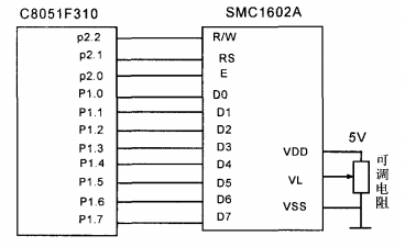
Liquid crystal display has many advantages such as small size, low power consumption, rich display content, ultra-thin and lightweight, so it has been more and more widely used in various instruments and low power application systems. This design uses the commonly used 2-wire 16-word SMC 1602A LCD module to display the measuring Angle. The connection diagram of SMC1602A LCD module and MCU is shown in Figure 4.
The P1 port of the MCU is connected to the data port of the SMC 1602A LCD module for data transmission and command. Port P2 Enables port R, R/W, and e. R S selects the terminal for data/commands, the number of command transfers per hour at high power and the number of command transfers per hour at low power. R/W is the read/write control terminal. High power read, low power write. When rs and R/W are in low power at the same time, instructions can be written or addresses can be displayed; When the SNR is low or high, the busy tone can be read. When RS is high and R/w is low, data can be written. E indicates the end of enabling. When E changes from high level to low level, the LCD module runs this command. D0 and D7 are 8-bit data cables. V L is the proportional adjustment end of the liquid crystal module,
The contrast is weakest when connected to a positive power supply, and the ratio is highest when grounded. When the ratio is too high, the "ghost" can be adjusted by a 10 kiloohms potentiometer.

FIG. 4 Connection diagram between MCU and SMC1602A LCD module
1. 6 RS-232 Communication module
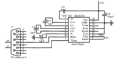
The system also provides communication between RS and host computer. Therefore, it is necessary to convert the transistor-transistor logic level of the TX-D end of the MCU to RS that the upper computer can receive. 232 level signal. In the RS.232 communication module, the main control chip is m&x2 32C PE chip of Meiya Communication Company. This chip can be used to turn transistors. Transistor logic levels are converted to RS-232 levels, and RS-232 levels can also be converted to transistors. Transistor logic level, a bidirectional drive receiver. The system uses the chip as the processing unit connected with the host computer to transmit the system signal data to the host computer. Users can collect the data of the inclination sensor system through the upper computer within the distance allowed by the RS-232 protocol, and can also easily use these data for reverse processing. The circuit is shown in Figure 5.

2. Software design
The software design also adopts the principle of modular design. The module program to achieve each function is made into a subroutine, and then called in the main program. According to the needs of the horizontal inclination measuring instrument system, it is divided into the following five sub-modules: MCU input and output initialization module, A/D converter initialization module, A/D converter data acquisition and sending to the MCU module, data transmission and display module to the liquid crystal module, rs.232 data transmission module. The software flow chart is shown in Figure 6, and the specific program code will not be repeated here.
3 Experimental verification
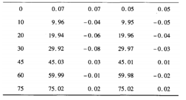
To test the performance of the system, use the Angle generator to set the instrument tilt Angle, each tilt 1. Record data once, from 0 to 90. Tests were performed and recorded in the positive and negative ranges, and two sets of data were finally obtained, as shown in Table 1. This tests the repeatability and linearity of the sensor. The least square method is used to fit the straight line, because it has the highest fitting accuracy. The equation of the fitted line is :Y = x10. 18, the linearity of the system is :A rnax /】, f = 0. 279/9 0 = 0. 00 31 (Am ax is the maximum deviation between the true characteristic curve and the fitted curve, and is the full scale output of the sensor). Minimum resolution 0.1°, sensitivity 2/90 0≈0.02}

Table 1 System performance test
4 knots
The new portable tilt sensor system designed by the author changes the power supply mode through the power management module, and realizes the dry battery power supply. The man-machine interface of display, RS-232 data transmission and other modes is controlled by microprocessor master unit. The original sensor products only have the interface mode of analog output, the product volume is reduced, and the body shell is cuboid shape. Body shell length X width x height = 120m x 80m x 40m m, mounting plate measuring surface length x width x height = 110r a m x 60m m X 35m m. The structural dimension of the machine is much smaller than that of the original traditional instrument with integrated structure, and its volume is smaller than that of the document [9], and it is easier to carry. The application of tilt sensor technology provides more new choices in the field of horizontal tilt Angle measurement, which meets the wide application needs of Angle measurement in industrial field.
References:
[1] Lu Weiping, Huang Mingfeng, Sun Yongrong. Application of Tilt Sensor in Solar energy tracking system [J]. Current Electrotron Technology, 2012, 35(1) : 129-13 1.
[2] Li Xiaohong. Development and Research of satellite antenna automatic positioning control System based on single chip [D]. Shanghai: East China Normal University, 2008. (in Chinese)
[3] Yang Xingyao, Liu Xingjing. High precision electronic tilt sensor and its Application in automatic leveling instrument [J]. Jiangsu Machinery Manufacturing & Automation, 1994, (6) : 34 -- 35.
[4] Guo Juncen, Zhou Junzhe, Tang Jian. Research on Automatic Leveling System of Tank Fire Control Debugging Platform based on Single chip machine [J]. Journal of Shenyang Polytechnic University, 2006, 25 (3) : 71-73.
[5] Tan Qing. Application of automatic leveling System in anti-aircraft fire [J]. Weapons and Equipment Automation, 2004, 23 (4) : 10-11.
[6] C h eng Y, W intertlood J, Ju L, et a1. T ilt sens or an dservoc on trolsys te m fo r grav itatio n al w av e d e te c tio n[J]. Q uantum G ravity. Q uantum g ravity. 2001, 7 (10) : 1723-1729.
[7] Le e Y Y, L ai n K C, Y ue n K K. A ctive vib ration controlof all aircraft c ab in pane l using piez oe le c tric sen sors an dactuators[J]. IEEE, 2003,3 (1) : 131-141.
[8] C h e n Y L. A p p lic atio n o f T ilt S en sor in H u m an - C o m p u ter M ouse Interface for People W ith Disablities [J]. A p p lic atio n o f t ilt s en sor in H u m an - c o m p U ter m ouse interface for people W ith disablities. IEEE, 1, 9 (3)


