Software realization of high precision temperature compensation for pressure sensor
This paper overcomes the shortcoming of traditional temperature compensation of pressure sensor by hardware circuit, introduces the basic method of temperature compensation of pressure sensor by single chip microcomputer, discusses how to use software to compensate temperature error, and describes the principle of software algorithm of high precision temperature compensation in detail, which provides a theoretical basis for realizing temperature compensation by software. The experimental results show that the output accuracy of the sensor with high precision temperature compensation algorithm is improved significantly.
0 Introduction
Pressure sensor is a common sensing element. Due to its own nonlinearity and the influence of external measurement conditions when used, most pressure sensors have nonlinear characteristics when output, so there are many factors of error. But among these error factors, the influence of temperature is the most obvious, so the sensor temperature error compensation is particularly important. It is very complicated and difficult to realize temperature error compensation by hardware compensation, but introducing software to realize temperature error compensation is a more effective method. As long as the temperature error compensation model is accurate enough, ideal results can be obtained. At the same time, it is hoped that the algorithm used is simple and efficient, avoiding the complex and time-consuming characteristics of temperature compensation algorithms such as BP network.
1. Traditional hardware compensation methods and their disadvantages
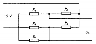
The traditional hardware temperature error compensation scheme is to parallel thermistor R on one or both bridge arms in a Whist bridge circuit, as shown in Figure 1. However, due to the characteristics of thermistor itself, it is impossible to achieve complete temperature error compensation. In addition, the realization of temperature error compensation through hardware circuit has some problems, such as inherent instability, difficulty in debugging, poor universality, high cost and low precision, which is not conducive to the practical application of engineering. Therefore, this paper introduces the software implementation of BE4 automatic detection and high precision temperature error compensation real-time control.

Figure 1 is combined with the thermistor temperature error compensation formula
2. Temperature compensation principle
In single-chip sensor measurement system, in order to solve the problem of sensor temperature error compensation, it is necessary to measure the temperature of the point where the sensor is located, so the temperature sensor is needed. The temperature sensor is usually mounted on the sensor near the sensitive element. Firstly, the temperature sensor is collected by A/D sampling circuit, and the corresponding output voltage signal (recorded as) is transmitted to the chip computer for temporary storage; Then the sensor output signal is amplified by the amplifier circuit, and collected by the A/D sampling circuit to the MCU; Finally, the temperature error compensation program is started. By searching the zero temperature drift voltage recorded in the single chip computer in advance, the final output voltage is:

3. Establishment of mathematical model of temperature compensation
3.1 Linear temperature compensation mathematical model
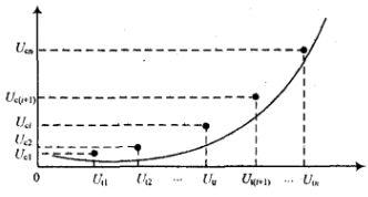
When compensating the temperature error, it is necessary to measure the voltage signal corresponding to each temperature value output by the temperature sensor on the given n temperature values in advance, and then measure the corresponding temperature drift voltage after the sensor output signal is amplified by the amplifier circuit at each temperature point to ensure the accuracy of the data. Measurements can be made in an incubator. The table is made and stored in the MCU memory, and then the mathematical model of the voltage signal and temperature drift voltage signal corresponding to the temperature value output by the temperature sensor is established. The characteristic curve Uo=F (Ut) is shown in Figure 3. We can divide the curve shown in Figure 3 into several sections, and the curve between adjacent two points is approximately regarded as a straight line, so that the temperature drift voltage corresponding to the voltage signal corresponding to a certain temperature value output by the temperature sensor can be obtained by linear method, which is the linear interpolation method. Assuming that the voltage signal corresponding to the output temperature value of the measured temperature sensor is one of the values, the corresponding temperature drift voltage is one of the corresponding values. If the voltage signal corresponding to the measured temperature output value of the temperature sensor is, the corresponding temperature drift voltage can be obtained from formula (2) :

From formula (2), it can be seen that good accuracy can be obtained if n is large enough, so that the microcontroller can obtain the corresponding zero temperature drift voltage through the voltage signal corresponding to the measured temperature.

Figure 3 Output voltage and temperature drift voltage characteristic curve of temperature sensor
3.2 Nonlinear temperature compensation numerical model
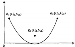
If the characteristic curves of the voltage signal and the temperature drift voltage signal corresponding to the output temperature value of the temperature sensor change greatly, the linear interpolation method will produce a large error. Therefore, the quadratic interpolation method can be used, as shown in Figure 4. A parabola is composed of three points K on a curve, but the equations of a quadratic parabola with one variable are A, B, and C. This equation requires simultaneous equations to find the value of 、、、、C, the calculation is complicated, the program is complicated. Take the following equation form:


Substitute G and into equation (3) to get another form of the equation:


It can be seen that the values of A, B and C can be obtained by using 3 known points K1, K2 and K3, and then put into the memory of the single chip microcomputer, and the corresponding values can be obtained according to the value of Ut. The above is the mathematical model of temperature error compensation for the sensor, and the temperature error compensation can be carried out with these two models.

FIG. 4 Interpolation method of conic curve
4. Design and implementation of temperature compensation software
The design flow chart of linear temperature compensation and nonlinear temperature compensation software is shown in Figure 5 and Figure 6. Because temperature is a continuous variable, in order to improve accuracy, the more temperature points collected, the higher the accuracy. The use of multi-bit A/D chips can ensure the needs of general circumstances. The software implementation process combined with single chip microcomputer is shown in Figure 7. The software design ensures that manual setting is not required, temperature changes are ensured in time, and the corresponding zero temperature drift voltage is found, so as to ensure that the output voltage of the MCU is updated in real time after the voltage value is corrected.
Step 5 Test
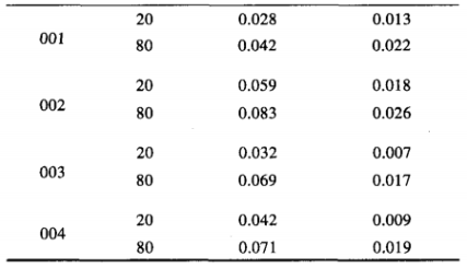
Table 1 shows the change of zero output of the transducer at 20℃ and 80℃. As can be seen from Table 1, the zero-bit output after software temperature compensation is significantly higher than that without software temperature compensation.
Table 2 shows the measurement results of the sensor at 25℃. As can be seen from Table 2, the accuracy after compensation is less than 1%.

Table 1 Zero output change before and after sensor compensation
6 Summary
In order to meet the application requirements of pressure sensor in high-precision occasions, the temperature error compensation of sensor combined with single-chip microcomputer is a very simple and effective method. This method can greatly reduce the circuit complexity and cost of the system, and the reliable value can be obtained without additional operation for ordinary users. It is suitable for the compensation of batch sensors and has a very broad application prospect.
Reference
[1] HU Liaolin, Liu Chen, Gai Guanghong. Research on intelligent energy temperature compensation for Silicon Piezoresistive Sensor [J]. Chinese Journal of Sensor Technology, 2012,25(4):468-471.
[2] Du Yongping, He Xiaoying. Discussion on sensor temperature compensation technology [J]. Electronic Design Engineering, 2009,17(6): 63.6 4.
[3] Sun Shenghe. Modern sensor development method [J]. Journal of Electronic Measurement and Instrument, 2009,23(1): 1-10.
[4] Guo Bing, Wang Chong. Current situation and development of pressure sensors [J]. China Instrument and Meter, 2009(5):7 2.7 5.
[5] Zeng Zhongbo. Analysis of zero drift solution for pressure sensor [J]. Science and Technology Outlook, 2013(34):100. 101.
[6] Zhang Hui. Pressure sensor data fusion based on bp neural network [J]. Journal of Hunan Institute of Technology, 2011,21(1):55. 5, 8.
[7] Teng Min. Derivation of zero temperature drift compensation formula for piezoresistive pressure sensor [J]. Journal of Henan Normal University: Natural Science Edition, 2011,39(1):101-103.
[8] Guan Rongfeng, Wang Xiaoxue. Temperature compensation of MEMS Pressure sensor [j]. Journal of Henan Normal University: Natural Science Edition, 2009,37 (1): 7o.73.
[9] Wang Shuhua. Current situation and application of EMMS sensor [j]. Micro and Nano Electronic Technology, 2011,48(8): 5-16. 52 twos.
[10] Wei Kaibin. Design and implementation of Temperature Compensation System for diffused Silicon Pressure Sensor [j]. Manufacturing Automation, 20,13,35(5):1 17 -- 119.
[11] Hu Yuanyuan, Li Huaijiang, Wang Dajun. Intelligent design of temperature compensation for pressure sensor based on ATm egal6 [J]. Instrument Technology and Sensor, 2010(10): 8-11


