


Design of high precision micro power consumption accessible digital pressure gauge based on MSP430
Using MPS430f149 as the total controller, the high precision micro power consumption pressure gauge is designed. The voltage sensor uses A constant current source for power supply, and the output uses a7714 for A/D conversion. The constant voltage generated by adr291 is used as the reference voltage. Modularized power supply and time-sharing data acquisition are adopted to reduce the power consumption of the system, and MSSFET power supply designed by ourselves is used to switch off the working module. The pressure data is filtered by means of mean filtering based on changing flow rate, and the pressure gauge is calibrated by multi-point calibration. A simplified file system is used to store and play back real-time pressure data. Pressure gauge accuracy reaches 0. More than 25%, in the case of using 4 batteries and 5 dry batteries, the normal continuous working time is more than 300h.
With the application of pressure measurement more and more widely, the demand for pressure measuring instruments is getting higher and higher. At present, the most widely used in industrial sites and scientific experiments are elastic pressure gauges and electronic pressure gauges: elastic pressure gauges due to years of development, should be widely used, mature technology pressure gauges, but the development space is small; With the continuous improvement of measurement automation range requirements, electronic pressure gauges have become the mainstream of pressure measurement. If the rapid development of information technology today puts forward high-precision requirements for electronic pressure gauges, coupled with the miniaturization and portability of measuring instruments, dry batteries have become the main power supply mode, and the capacity of dry batteries is limited. This puts forward higher requirements for the micro power consumption of measuring instruments.
1 Overall system design
The purpose of this system is to design a digital pressure gauge with high precision and micro power consumption, so high precision and micro power consumption are the focus and difficulty of this design, which must be considered from the overall design. The total system power consumption generally includes component-level power consumption and system-level power consumption. It is necessary to start from these two aspects to achieve the purpose of micro-power consumption of the system.
The overall framework of the system is mainly composed of power pipeline management module, reference voltage module, constant current source, pressure data acquisition module, liquid crystal display module, serial communication module, temperature sampling module and key circuits.
MSP430 series microcontroller is an ultra-low power mixed signal processor, which can be used for power supply units with long waiting time. The active clock source enables the device to realize the lowest power consumption; The digitally controlled shaker (DAC O) allows the device to quickly wake up from low-power mode and activate to live operating mode in less than 6 lxs. Considering the micro-power requirement of this system, MSP430F149 is selected as the total controller. The pressure sensor adopts M E A S company 87N. The sensor has good linearity, small temperature error and low power consumption, which meets the requirements of high precision and low power consumption in the design of this system.
2 Hardware Design
2.1 Power Management Module
The system adopts a modular power supply and time planning mechanism, which can disconnect the power supply when the module is not working to reduce power consumption. Using the MA X 883 and MA X 884 as the system's 5v and 3.3V power supplies, these two cores are low-difference linear regulator cores with a static current of only 1a in the lowest power operating mode. It can fully meet the micro-power requirements of the system.
The system uses one MA X 883 and two MA X 884 to supply power to each module. In the experiment, a MAX 884 tablet produced cpu 3. 3v is normally on, and the other two power supplies can be controlled by the single chip microcomputer when the pressure gauge is turned off. The power switch is also designed for N channel and P channel, because the temperature acquisition module and serial communication module are not commonly used, so the power switch is configured for these two modules. The power switch is controlled on and off through the I / 0 port of the microcontroller to reduce power consumption.
In addition, due to the large power consumption of the LCD backlight, the battery direct power supply strategy is used to control the current limiting resistance of different resistance values through the on-off of MFSF
2.2 Pressure data acquisition module
The MSP4 30f149 MCU contains A 12-bit A/D conversion module and an optional 1. 2, 5v and 2. 5v refers to the voltage module, so many pressure gauges directly use the internal A/D module and reference voltage. While this simplifies the system structure, the direct connection limits the accuracy of the manometer. The pressure data acquisition module of the system includes the acquisition and conversion of pressure data, the pressure sensor is powered by the constant current source, and the output is amplified from the ad7714 to A/D output. The reference voltage of the d7714 is generated by an external reference voltage circuit.
2. 2. 1 Consider voltage circuits
The reference voltage used in this system is generated by AD-R291, which is a low noise and low power consumption reference voltage chip. The reference voltage circuit is shown in Figure 2, which produces 2. The accuracy of 5V reference voltage is more than 0.12%, which meets the high precision requirement of this system. 2. Put out the 5V resistor to generate 1. 25V is used as the reference voltage of A/D chip. In order to improve the accuracy of the reference voltage of A/D chip, both R33 and R34 in Figure 2 adopt a high-precision resistance of 1‰.
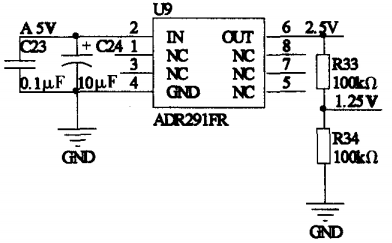
Figure 2 shows the voltage circuit
2. 2. 2 Constant current source circuit
The measuring circuit inside the pressure sensor used in this system is a full-bridge differential circuit, and the power supply of the bridge can be a constant voltage source or a constant current source. In order to reduce the shadow of temperature and improve the measurement accuracy, the system uses a constant current source to power the pressure sensor.
At the heart of the constant current source circuit is the opa335, which is a self-zeroing, single-power operational amplifier. The maximum offset voltage of the system is 5v and the static current is 285 A, which has the requirements of high precision and low power consumption. The constant current source circuit is shown in Figure 3, utilizing the "virtual short" and "virtual break" characteristics of the op amp, where the resistors R29, R31, and R32 are all 1%. The high precision resistance of the pressure sensor generates a constant current source of 806a, and the I + and I components are the positive and negative power inputs of the pressure sensor, respectively. The test shows that the constant current source is stable and reliable when the load impedance is less than 5 kQ, and the system pressure sensor is needed to supply power.
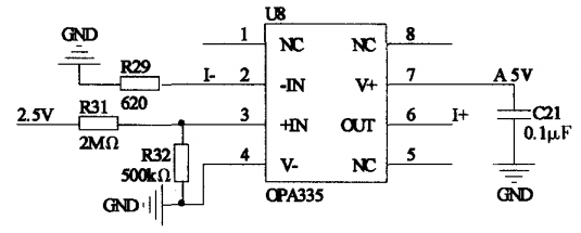
Figure 3 Constant current source circuit
2. 2. 3 A/D conversion circuit
Since the 12-bit A/D integrated in MSP4 30F149 microcontroller can not meet the high precision requirements of full-size system, considering the micro-power requirements of the system, the 24-bit A/D chip ad77 14Y RU is finally selected. The chip is able to utilize sum difference conversion technology to achieve error-free coding performance of up to 24 bits, with 0. 15% nonlinearity. In addition, the internal package of the chip contains a programmable amplifier (PGA) that can amplify the small signal size up to 128 times, saving the design of high-precision small signal amplification circuits in the circuit and simplifying the system structure.
When designing the d7714 external circuit, special attention should be paid to the digital power supply and analog power supply separately, and the digital ground wire is grounded after the O-FT resistance to avoid dry interference with each other.
3 Software Design
3.1 minutes data collection
The MSP430 has one active mode and five low power modes, which can be set to enter the corresponding low power mode from the active mode, and can also enter various low power modes through interrupt mode. The power consumption of MSP430 varies greatly in different operating modes, and the power consumption of medium and low power mode 3 (LP M3) and low power mode 4(LM P4) systems is quite low, basically negligible.
The system adopts the strategy of collecting time data, that is, according to the set food conditions to collect different data information, such as pressure, temperature, battery voltage and so on. Taking pressure data collection as an example, data collection is not carried out once per program cycle, but is collected according to time information. The system program is set to every 0. 1s enter intermittent interrupt, exit Low power mode 3 in intermittent interrupt, enter active mode, program cycle once, and then enter low power mode 3 (LPC3). At the same time, the program is executed in the loop to make judgments between times, such as whether the interval reaches 0. 4 seconds, read A pressure data, and perform A/D conversion. The total program flow of the system is shown in Figure 4.
3.2 Variable speed average filter wave
The experimental results show that the simple mean filtering method can not meet the real-time and stability requirements of the system. For this reason, the filtration method of the valve body is determined according to the rate of change of the pressure data. When the pressure data changes quickly, the average filtering method of less points is adopted to ensure the real-time display of the pressure gauge data. In order to ensure the stability of pressure gauge display data when the pressure data changes slowly, the middle part average method is used to sort the points.
First, the pressure data is collected, and then it is determined whether the direction of change of the pressure data is the same for two consecutive times. If not, return directly. If they are the same, then use a recursive formula to divide the pressure data into several groups, and then judge the following formula:
3.3 Multi-point calibration and linear interpolation values
It is found that even if the normal pressure sensor is powered by constant current source, its output and input do not show a simple linear relationship, which brings difficulties to calibration. For pressure gauges with low accuracy, full scale and zero calibration formulas are generally used. The actual test shows that the calibration formula can not meet the calibration requirements of high precision system. Therefore, the system uses a multi-point calibration formula to approximate the output curve of the pressure sensor with multiple line segments (Figure 5).
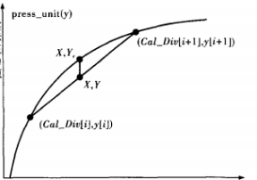
FIG. 5 Multi-point calibration and linear interpolation
The system finally adopts an 11-point calibration formula, that is, full scale 0%, 10%, 20%,... After the calibration is complete, the calibration data Cal_D iv [i] is stored in the Flash data store. When calculating the current pressure value, the obtained current pressure data is first compared with the calibration data C al-D iv [i], and the interval where the current pressure data is located is obtained. Linear interpolation method is used to calculate the current pressure value:
The comparison data of the full range, zero calibration formula and 11-point calibration formula obtained by the experiment are shown in Table 1.
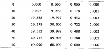
It can be seen from Table 1 that the two-point calibration formula has higher accuracy near 0 point and full scale point, while the error difference in the middle section is larger and the accuracy is lower. Therefore, the two-point calibration method is only suitable for low precision occasions. The multi-point calibration formula used in the system can fit the output curve of the pressure sensor more accurately, improve the measurement accuracy in a wide range, and meet the requirements of the system for high precision pressure measurement.
3.4 Data Storage and Playback
The system designed a data storage mechanism based on MSP430 large capacity flash memory, which can store the pressure data and pressure calibration value collected by the pressure gauge in real time, to ensure that the data is not lost in the case of machine shutdown or power failure. And provide data playback function, query historical storage data.
Because the MCU MSP430 F149 used in this system has 64kb Flash, in addition to occupying its internal resources, there are 60kb code storage space and 256b segment A and B segment information memory. Fully meet system data storage requirements. Segment A information store stores the pressure calibration values of the storage system to ensure that data is not lost after the pressure gauge is calibrated once. In addition, 10KB of the 60KB of code storage space is reserved for the storage of real-time pressure data. In the storage system, write a simple document system to manage and store data, that is, use the document group to store data. Due to the limitation of storage space, the system can store up to 40 files, each file can store 20 points of pressure data, and add the zero function, when the data is full, you can manually empty the entire file storage area. Ensure data storage continuity. Through practical operation, the simplified file system can meet the functions of real-time data storage and query playback, and can also upload the stored data to the host computer through RS232 communication interface for viewing.
4 Closing remarks
The design of digital manometer with high precision, low power consumption and storage is introduced systematically. The methods of realizing high precision and low power consumption are described from two aspects of hardware and software, and the methods of data storage and playback are given. Finally, the experimental comparison data is given, and the measuring error of the pressure gauge is analyzed. The experiment shows that the measuring accuracy of the pressure gauge can reach 0. 25%0, under the condition of 4 and 5 dry batteries, the normal continuous working time can reach more than 3 000 hours. This design will promote the development of portable and miniature watt-hour meters, and lay a foundation for electronic and digital measurement information.
References:
[1] Zheng Liping, Huang Tao, Wu Wuchen, et al. Research on Digital Pressure Gauge for Artillery based on Ultra-low power Consumption design [J]. Sensors and Instruments, 2009,25 (7):82 ~ 83,8
[2] Wei Xiaolong. Msp430 series microcontroller interface technology and system design example [M]. Beijing: Beijing University of Aeronautics and Astronautics Press, 20002.
[3] He Weixing, Wang Bin, Wu Wenya, et al. Design of high precision manometer based on msp430 [J]. Chemical Automation & Instrumentation, 2010,3,7 (12):70
[4] Xu Kejun, Ma Xiushui, Li Xiaolin, et al. Sensor and detection technology [M]. The second edition. Beijing: Publishing House of Electronics Industry, 2011.
[5] GUO Gongjiu, Xiao Changqing, Fang Ying. Design of Dual-wire intelligent pH Converter based on msp430 single chip microcomputer [J]. Chemical Automation & Instrumentation, 2011,38(8):10 16 -- 10 19.
[6] Aileen. Design and implementation of digital pressure gauge based on msp430 single chip microcomputer [D]. Shenyang: Northeastern University, 2004. (in Chinese) (Chinese)