High precision pressure sensor design for satellite
The technical requirements, working principle, structure design, circuit design and test results of high precision satellite pressure sensor are introduced. The key technologies and solutions in the development process are discussed. Based on the principle of silicon micropiezoresistive effect, the sensor adopts related semiconductor plane technology, micromachining technology and signal conditioning compensation technology in the electronic circuit, and integrates the pressure sensitive element and conditioning circuit in the shell. The sensor has the characteristics of good nonlinear, wide operating temperature range, shock overload resistance, stable and reliable performance, etc.
Satellites carry out a large number of scientific, military and civilian missions in flight, and the pressure in the sealed cavity is necessary to ensure the normal operation of many equipment. For example, with satellite photography and phase systems, if there is no normal atmospheric pressure on the ground, the camera will not be clear. A satellite high precision pressure sensor for pressure measurement and control of sealed chamber was developed. Its successful development has practical significance for breaking the foreign arms blockade and speeding up the modernization of domestic arms and equipment.
1 Analysis of key indicators
1.1 Nonlinearity
Nonlinearity is one of the three factors that affect the static accuracy of sensors. In order to ensure the high precision of the sensor, the index must be improved. For small range piezoresistive piezoelectric transducers, the nonlinearity of piezoresistive piezoelectric transducers should be in the range of 0.5% FS to 0.2% FS. In order to ensure the high precision of the sensor, the nonlinear compensation is designed so that the nonlinear of the sensor is 0. In the 1% FS range.
1.2 Zero drift (Stability)
Zero drift is the measurement of the stability of the sensor in a short time, and it is also the premise of the sensor to ensure the long-term measurement stability. Only the zero drift index of the pressure sensor is small enough to ensure the long-term control accuracy of the pressure in the satellite sealed cavity. When designing pressure sensitive components and conditioning circuits, attention should be paid to the matching of signals, and attention should be paid to the selection of components to reduce output drift.
1.3 Pulse Overload
The demand for this indicator is high, at 1500g. Therefore, guarantee should be given in the overall structural design.
2 Working Principle
2.1 Working principle of pressure sensitive elements
The pressure sensor adopts the principle of piezoresistive effect, and uses semiconductor technology and micro-machining technology to form Wheatstone bridge on semiconductor monocrystalline silicon, and converts the measured pressure into voltage signal.
Figure 1 is a schematic diagram of the Wheatstone bridge. In an electrical parallelogram consisting of 4 resistors, when a constant current is applied to one set of diagonal points, the output voltage △U is generated statically at the other set of diagonal points, the value of which is given by the following formula:

For piezoresistive pressure sensors, when the device does not feel the pressure, the four resistors do not change, the sensor output is zero output, at this time, △U static =U0. In terms of usage, the smaller the better. When the device feels the pressure, the resistance R1, R3, the resistance value increases; R2, R4 resistance decreases, resulting in an electrical output proportional to the pressure △U static.
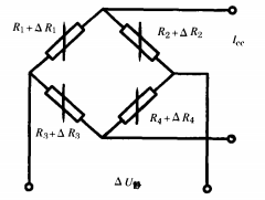
FIG. 1 Schematic diagram of Wheatstone Bridge
2.2 Working principle of the sensor
The pressure sensor converts the pressure into a voltage signal that is △u static through its core component, and then adjusts the signal to meet the contract requirements through the conditioning circuit.
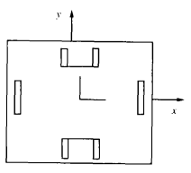
(a) Resistance distribution diagram of square silicon cup
The part in the dashed box in Figure 2 is the conditioning circuit. It includes circuit protection, filtering, constant current power supply, linear compensation, amplification and other parts, each part of the circuit to complete the internal and external protection, interference filtering, pressure sensitive element constant current power supply and temperature compensation, output signal linear compensation, output signal amplification and other functions.
3 Overall scheme design
3.1 Overall structure design
The overall structure of the sensor consists of two main components: the connector and the housing. It has been carefully designed to make it compact, small and functional. The joint completes several functions: sealing installation of pressure sensitive components, installation of fixed conditioning circuit board, full range pressure sealing test; The housing has the function of containing all internal components of the sensor, electrical connection mounting and sensor mounting fixation. The body is filled with glue to improve the vibration resistance and impact resistance of the shell. The structure design of the pressure sensor is based on the range and structure requirements of the sensor. The whole structure of the pressure sensitive element is composed of the pressure sensitive element shell, rectangular double island silicon film, outer lead, thick film compensation plate, substrate, electrostatic sealing base, inner lead, protective adhesive, etc. The sensitive element of the sensor is formed on the monocrystalline silicon with the thickness of the corresponding sensor range, and then through microelectronics technology, four variable resistors are formed on the elastic diaphragm to form a Wheatstone bridge. When compressive force is applied, the elastic membrane deforms, forming two positive and negative strain zones, and the resistivity of the material changes accordingly. The pressure sensing element of the transducer is a square thin film with good technology and excellent performance. The stress distribution on the Wheatstone bridge resistance and elastic diaphragm with square diaphragm arrangement is shown in Figure 3.
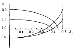
(b) Stress distribution
3.2 Circuit Design
1) Conditioning circuit principle design
The design criterion of the conditioning circuit is to meet the performance requirements of the contract under the premise of ensuring reliability and safety. The conditioning circuit includes circuit protection, filtering, constant current power supply, linear compensation, amplification and other parts, and each part completes the internal and external protection of the circuit, interference dynamic filtering, liquid level (pressure) sensor constant current power supply and temperature compensation, linear compensation, output signal amplification and other functions.
2) Circuit board design
In the design process of the printed circuit board, in order to reduce the radiation emission of the electronic circuit and reduce the ring area formed by the differential film radiation caused by the current flowing through the circuit wire, the design and treatment criteria of the printed circuit components should comply with the basic principles and provisions of GJB362-96 "Design and Use of Printed Circuit Board". Because the thin and long loop has a high inductance, its impedance increases with the increase of frequency. To avoid causing impedance coupling, use copper foil plates and the widest possible wiring. When wiring the power supply, under the consideration of safety conditions, the power line is as close as possible to the ground wire to reduce the ring area of the differential film radiation, which also helps to reduce the interference of the circuit. In addition, the discontinuity of the printed circuit board wire is avoided, and the wire width is designed without mutation and the wire has no mutation Angle. In order to improve the process reliability of the sensor, the connection between the printed circuit board and the external lead is designed to make the connection between the lead and the circuit board more reliable. The electrical connection between the leads of each function and the external part can be double-wire connection to increase reliability. The selection of electronic components is the basis of electronic technology, and its quality grade and characteristics must meet the requirements of design and use. Circuit filtering, grounding and shielding design is part of circuit board design. The filter, grounding and shielding design of the circuit is designed for the three elements of electromagnetic interference, namely, the interference source, the propagation path and the sensitive device. The combination of circuit design and structure design, the combination of lap, ground and shield, so that the filter can best meet the design requirements. Circuit protection design is also part of circuit board design. The sensor design itself has no induction components, no radiation source, and the internal one-time all-adhesive tank seal not only enhances the sensor's ability to resist shock and vibration, improves reliability, and does not cause harm to the external environment equipment. The input and output of the sensor are designed with electrical protection, the input power is reversed, the output short circuit and part of the circuit damage, and the output voltage greater than 5.6V and less than 0.85v will not cause damage to the system. The rationality of the circuit has been verified in the actual flight of the product.
3.3 Reliability Design
1) Reliability design of pressure sensitive components
The material of the pressure sensor is monocrystalline silicon. Because the material is a hard and brittle material, a large margin must be left when designing the elastic structure to ensure the reliability of the sensor. For the safety of the pressure-sensitive element used in the sensor, according to the particularity of its working structure, the longitudinal stress and transverse stress that the diaphragm may feel can be substituted into the following formula by the strength energy theory in elasticity

When the equivalent stress is less than or close to the maximum allowable stress in the elastic limit, the maximum stress of the elastic element can be adopted. Otherwise it must be redesigned. In order to ensure that the sensor has a high enough safety, d is usually less than 1.5 to 2 times the elastic limit.
2) The reliability design of the conditioning circuit
Under the premise of meeting the requirements of the technical indicators of the customer, the design is simplified, the circuit is reduced, and the corresponding function is realized with the least components. In the design of sensor circuit, anti-interference and radiation shielding are used to improve the ability to resist strong electromagnetic interference. The input and output terminals adopt polarity and overvoltage protection measures to avoid damage to the sensor caused by reverse power connection or short circuit between the output and the power supply. The input and output electrical cables are connected with the circuit board with process holes, and the electrical connectors are connected with single-function double-wire connections to the maximum extent.
3) Structural reliability design
In structural design, the simplest possible structure is used to complete the requirements of the target, and the strength check is carried out at all joints and dangerous structures, and the reliability is predicted according to the calculated stress and reliability stress distribution theory: According to the stress strength interference theory, the working stress of the structural part is, and the strength of the material (such as tensile strength of duralumin, shear strength of adhesive, etc.) is, assuming that both are subject to normal distribution, as shown in Figure 4
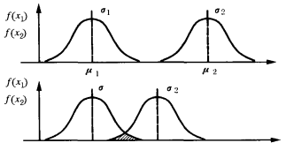
Note: average value of stress; : indicates the mean strength; Is the standard deviation of the stress; Is the standard deviation of the intensity. FIG. 4 Stress intensity interference model
4. Research on key technologies
4.1 Measures to enhance anti-electromagnetic interference capability
The shape and weight of the sensor have been determined by practical engineering, and the filter circuit must be simple and practical. This design makes the DC of the sensor conditioning circuit not independently grounded (grounded), but realizes AC grounding through the high-frequency capacitor, so that the interference has its own path, reduces the need to increase the filter circuit function of more components, and realizes the sensor and the system double point grounding. This not only greatly improves the anti-electromagnetic interference capability of the sensor, but also does not add more components. The method has been verified in practical engineering application.
4.2 Grinding and shielding technology
A good connection is a guarantee of grounding and shielding (anti-interference). In the design process of the sensor, a total of 7 overlapping points were designed inside and outside to ensure a good overlap between the sensor and the system. The use of shielded cables prevents unwanted radiation and external interference. In order to obtain the maximum shielding efficiency, the ground impedance at the end of the shielding layer is required to be very low, that is, there is a very small bond resistance. One end of the shield layer of the cable is connected with the shell of the sensor, and the other end is connected with the ground. There is an insulating sheath outside the shield layer to ensure its shielding effect.
4.3 Nonlinear compensation technology
Nonlinear compensation is through the resistance loop output transducer, feedback to the power supply of the pressure sensor, control the power supply of the pressure sensor, to achieve the purpose of nonlinear compensation. For a positive nonlinear pressure-sensitive element, the inverting input of a constant current source op amp requires feedback, and vice versa.
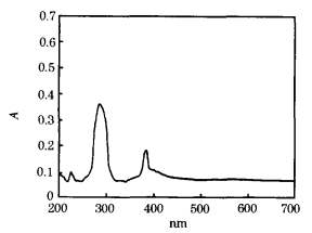
c. Methyl orange (5h)
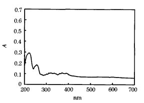
d. Congo Red (5h)
Figure 2 UV-VIS absorption spectra of methyl orange and Congo red
2.4 Degree of mineralization
The initial TOC values of 0.01mmol/L methyl orange and Congo red solutions were 15.72mg/L and 45.89mg/L, respectively. After 5h reaction, TOC values were 2.75mg/L and 5.23mg/L, respectively, TOC removal rates were 82.5% and 88.6%, and the mineralization degree was good.
Three knots
In the electrocatalytic system of Ti/Sn and Sb oxide anodes, the chromaticity of methyl orange and Congo red is completely removed at a fast rate, but the mineralization process is slow. Chrominance removal generally only goes through one step reaction, and the color group is destroyed. The molecular structure of methyl orange and Congo red is complex, its ring opening and chain breaking are complicated, and the process of conversion into co2 is complex and susceptible to interference, so it is slow.
References:
[1] HSIAO Y, NOBE K.O xidativereactionsofphenolandehloro - benzenewithin setupelectrogeneratedFenton 'sreagent [J]. Chem.Eng.Com mon. Journal of Natural Sciences, 1993, 126(1) : 97 -- 110.
[2] Wang Yuling, CAI Naicai, Zhang Huaisong. Novel reaction system for degradation of organic toxicants in water [J]. Journal of Chemistry, 2002,23 (10) : 1969-1973.
[3] Li Qingshan, Zhang Jinchao. Effect of co-precipitation conditions on particle size and electrical properties of nano-Sb/SnO2 [J]. Chinese Journal of Applied Chemistry, 2002, 19(2) : 163-167.


