Systematic calibration of ultra-short baseline underwater sound
In the application of positioning, the ultra-short baseline should be installed on the surface ship and combined with the global positioning System DGPS, attitude sensor VRU and compass GYRO to complete the final positioning. The relative distance and azimuth of the transducer measured by the ultra-short baseline should be calculated under the absolute coordinate system of GPS. In the process of calculation, The direction of the transducer is reduced to the head of the ship, and the attitude is reduced to the attitude of the ship, which is the process of calibration. This paper will elaborate the calibration method of the ultra-short baseline.
1. Working principle of ultra-short baseline positioning
Ultra Short Baseline Positioning System (USBL) Acoustic systems use a single sensor consisting of four or more components (see Figure 1) to locate the target by acoustic measurements that determine the distance and orientation of the target relative to the hydrophone. The ultra Short Baseline positioning System (USBL) principle is based on an array of acoustic sensors that are mounted in a single transceiver (hydrophone) assembly and deployed on a surface vessel.
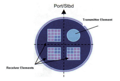
Figure 1 USBL sensor transmitter/receiver element
The underwater positioning of the ultra-short baseline acoustic system is to solve the azimuth by accurately measuring the phase difference of the acoustic signal received by the two sensors (carrier frequency f), and solve the distance by measuring the time difference between the sending of the inquiry signal and the receiving of the response signal. Systems using sinusoidal signals measure the "time phase" of the signal in each element (see Figure 2), in relation to the receiver's reference. An inquiry pulse is transmitted from the ship, the reference sensor, to the queried seabed transponder, and the reply pulse is sent back to the sensor. If a compass and surface navigation system are connected to the system, the north reference position and absolute position of the transponder can be calculated by triangulation (see Figure 3).
2. Purpose of system calibration
During the USBL installation process, there are installation and systematic errors in the reference direction of the transmitting/receiving primitive and the direction of the horizontal reference frame of the ship, as well as in the plane where the primitive is located and the direction of the vertical reference frame of the ship. The purpose of calibration is to eliminate these errors and calibrate the horizontal deviation, pitch deviation and roll deviation through specific methods of data acquisition, so as to improve the accuracy of positioning.
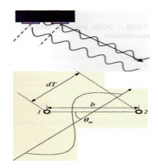
FIG. 2 Phase delay and incidence Angle
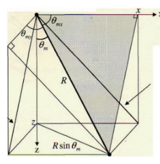
FIG. 3 USBL geometry
3 Implementation of system calibration
3.1 Data Collection
Before the formal launch of system calibration, it is necessary to conduct compass inspection and calibration, attitude sensor inspection and calibration, sound velocity acquisition and application, offset measurement and application. Calibration of the compass requires the alignment of the compass measurements to the ship's center line, using total stations, using known points or solar observations. During the calibration of the ship attitude sensor, the measurement data of the sensor is calculated to the ship's reference system. The real-time relative elevation measurement can be carried out by means of two total stations or RTK. The sound velocity acquisition uses the sound velocity transducer to measure the sound velocity of the whole water depth, which can be released by the winch or carried by the ROV. The measurement of offset is to measure the square of the Y-axis with the ship's center line pointing to the ship's bow, establish a right-handed coordinate system, and use the total station to measure the position of the reference point in the coordinate system. After the above preparation work is completed, a transponder is arranged on the seabed, and the answer is fixed by tripod or heavy block plus float ball. The distance from the seabed is 1.5 ~ 2m. After the test communication is normal, the data collection work is ready to start.
3.2 Data Collection
On dynamically positioned ships, the preferred method for data collection is the fixed point method. In order to obtain more accurate calibration results, the ship should keep the same direction as far as possible during data acquisition at the four selected base points. In deep water, the base point is usually chosen at 1/3 or 500m from the depth of the beacon, whichever is less. This reduces the amount of communication bending that can occur and ensures that the communication has the best signal-to-noise ratio. If the quality of data collection is not reasonable, the ship can be turned around, as shown in Figure 5, and data collection can be conducted again according to the data of 1, center, 3,4, center, and 2, so as to ensure that sufficient data can be collected, and at least 100 groups of data can be collected in each direction of each base point.
On non-DP ships, it is difficult to maintain a constant course and position. Therefore, various other methods can be used to collect data, such as eight-leaf graphs, clover leaves or double-triangle methods (see Figure 6).
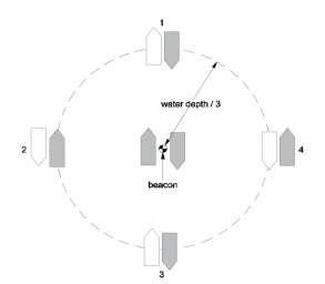
Figure 5. Cardinality calibration contour
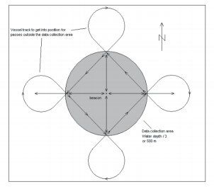
Figure 6 Calibration by running line
USBL systems should not be calibrated in less than 100m of water if possible. If calibration must be carried out in less than 100m of water, then data can only be collected by running lines in opposite directions in a box and a cross pattern centered on the transmitter transponder. Figure 7 is a typical data acquisition pattern.
A total of 12 lines are run between the two adjacent base points and four transitions are made at the top of the beacon. The orientation of the line can be rotated to provide current and wind direction where needed. The length of the running line depends on the water depth at which the fixed data is collected. Before data collection begins, the line should be extended by an appropriate distance to allow the ship to stabilize its course.
3.3 Data Processing
Processing software usually uses least square method to solve unknowns. When the inverse value of the error is used as the weight in the adjustment process, the initial value and error should be given for the unknown. Error estimates should be realistic.
The following error estimates represent a typical boat setup.
Beacon position +/- 50m
Beacon depth +/- 10m
Sound speed +/- 3m
Offset +/ -1m
During processing, make sure that at least 2/3 of the data is available so that the calibration results are more reliable.
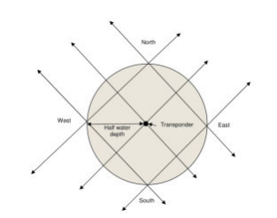
FIG. 7 Ship passing calibration line (water depth greater than 100m)
3.4 Result Verification
The purpose of system verification is to ensure that the calibration results are reliable and reliable. This test is usually performed at the end of field calibration, but can also be used to verify that a system has been calibrated without the need for a full calibration. In this case, a full field calibration may be required if the verification results indicate a possible systematic error in the system. For system verification, the distance between the ship and the deployed beacon is set to 30m or 40m (normal ROV operating range). As with the rotation test, the ship will rotate 360° around the sensor while observing and recording USBL data. Record at least 200 points. The system is considered calibrated if the final results show no systematic bias and meet the normally expected accuracy of the system for water depth and environmental conditions during the test.
4 Closing Remarks
Before using the USBL positioning system, ensure that the system has been calibrated. The calibration process should take into account current weather/sea conditions to minimize acoustic interference from thrusters and wave noise. Marine conditions need to be considered, and the effects of light bending (refraction and reflection) can adversely affect calibration if extreme chloride ions or thermocline are present in the water layer. In newer systems such as HiPAP/APOS, sound velocity can be accurately modeled within the USBL system. On older systems, you can only input the speed of sound for the sensor, intermediate water and transponder position. In addition, the quality of the surface positioning system should be monitored during the USBL calibration process, as any errors from the surface positioning system are transmitted directly to the USBL system and can affect the calibration results.
References:
[1] YU Min. Development of Long-Range Ultra-Short Baseline Positioning System [D]. Harbin: Harbin Engineering University,2005.
[2] Liu Yanxiong, Peng Lin, Wu Yongting, et al. Research on Calibration Method of underwater acoustic Positioning System for Ultrashimar base line [J]. Information Science of Wuhan University,2006(7): 610-612.
[3] Niu Qingzheng. Design and implementation of Ultra Short Baseline Positioning System Detection Device [D]. Harbin: Harbin Engineering University,2017.


