Application of ultra short baseline positioning system in measuring and controlling immersed tube
With the development of water traffic, it is difficult for a single sinking tube positioning method to meet the needs of construction. With the development of sinking tube construction environment to far shore and deep water, a variety of positioning methods are combined and integrated into a comprehensive positioning system has become the mainstream of modern sinking tube tunnel positioning technology. The geodetic coordinates of submerged tube can be obtained by combining underwater acoustic positioning technology with wide-area differential GPS positioning technology, which is less affected by environmental factors and does not require the installation of measuring tower, so it has become an effective way to solve the sinking of pipe joint in deep-water submerged tube tunnel.
It is put forward that the sinking location of the sink tube can be divided into two stages: coarse measuring stage and fine measuring stage. In the rough measurement stage, the ultra short baseline (USBL) acoustic positioning system is combined with GPS to conduct real-time measurement of the pipe joint pose in the sinking stage, guide the pipe joint to be sunk to the predetermined position, save the installation of the measuring tower and improve the construction depth. In the fine measurement stage, the final joint of the sunk pipe is completed by the fine positioning system (such as ultrasonic positioning and mechanical positioning). Focusing on the phase of rough measurement, this paper gives a detailed scheme of sinking tube positioning based on underwater acoustic positioning system and GPS positioning system.
1. Sinking tube positioning scheme
1. 1 Scheme layout
In view of the sinking stage of the pipeline to be sunk, the ultra-short baseline positioning system is proposed to measure and control the attitude of the sunk pipe joint in real time. The ultra-short baseline system installed on the side of the construction platform (such as barge) uses sound wave as the carrier to locate the transponder fixed on the surface of the pipe section to be sunk. The barge is installed with GPS antenna and attitude sensor, which is used to convert the positioning information under the ultra-short baseline coordinate system into geodetic coordinates. Therefore, three coordinate systems need to be established: The geodetic coordinate system with the GPS antenna as the origin, the ship's center coordinate system with the barge's center of gravity as the origin, and the base array coordinate system with the ultra-short base array center as the origin. Through the ship's attitude information measured by the attitude sensor and the geodetic coordinates of the GPS antenna, the three coordinate systems are converted according to the Euler rotation matrix, and finally the position and pose information of the sinking tube in the geodetic coordinate system can be obtained.
From the sinking of the tube section, the transponder located on the upper surface of the sink tube will continuously emit preset pulse signals, and the array continues to receive pulse signals. The ultra-short baseline system calculates the position of the transponder in the array coordinate system according to the phase difference between the base interval elements, and obtains the position and pose information of the sink tube through the pose solution method. Then, the absolute position and pose information of sunk tube in geodetic coordinate system is obtained through coordinate transformation. Finally, the display displays the three-dimensional position and pose of sunk tube in geodetic coordinate system in real time to carry out continuous monitoring on the site construction.
1. 2 pose solution
Given that the transponder is installed on the pipe segment to be sunk, and the transponder on the pipe segment to be sunk is on a plane, three points on the plane of the pipe segment to be sunk can be obtained by solving the coordinates of the transponder according to the conditions of three-point coplane, and then the attitude information of the plane of the pipe segment to be sunk in the matrix coordinate system.
Let the plane equation of the pipe joint plane to be sunk be

In the formula, A, B and C are unknown parameters, and at least 3 non-collinear coordinates are required. After solving A, B and C, the normal vector of the pipe joint plane to be sunk in the matrix coordinate system can be obtained through the normal equation of the plane, that is, the direction cosine vector of the pipe joint plane to be sunk.

Suppose the plane where the USBL matrix is located is XOY, then the normal vector of the matrix plane can be expressed as

Then, the rotation matrix from the pipe joint plane normal vector to the USBL matrix plane normal vector can be expressed as

Let the Euler Angle of rotation around the matrix axis from the USBL plane to the immersed pipe joint plane be θx, θy and θz, then R is the rotation matrix of θx, θy and θz, and the attitude Angle of the immersed pipe joint plane can be obtained according to the rotation matrix R.
1.3 Multiple access location technology
From the pose solution method, the submerged tube positioning process needs to be multiple transponders (≥3) for positioning, so it involves underwater multiple access positioning technology, that is, each transponder through the transmission of different forms of pulse signal, ultra short baseline system according to the pulse signal received to distinguish different transponders, and determine the coordinates of each transponder in the matrix coordinate system, Notch filter can be used as multi-access signal detector and phase difference estimator for ultra-short baseline systems due to its ability to adjust parameters and its low requirement for prior knowledge of signal and noise, as well as its good phase difference estimation ability at high signal-to-noise ratio.
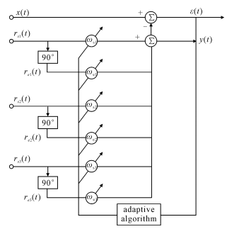
Firstly, the available bandwidth is designed according to the number of transponders. The frequency of each Notch reference signal corresponds to the center frequency of the transponder. Assuming that three transponders need to be installed, the corresponding three-channel parallel Notch filter structure diagram is shown in Figure 2.
X(t) is received by the array for each transponder

Where :n(t) is background noise

Figure 2. Notch filter in 3-channel parallel
ri(t) is the two orthogonal reference signals, y(t) is the inner product of the orthogonal signal of the reference signal, and ε(t) is the error of the inner product of the received signal and the reference signal. The frequency of the reference signal is known, corresponding to the center frequency of the signal transmitted by a single transponder.

Where, A is the amplitude of the reference signal and the subscript i represents the identity number of the transponder i = 1, 2, 3
Each signal received by the array passes through the Notch filter in three parallel channels. By selecting the appropriate adaptive algorithm, the corresponding transponder to which the signal is sent can be detected through the output result of the filter, and then the phase difference between adjacent elements of the array can be solved by the phase difference estimation.

In the formula: subscript i represents the identity of the transponder m and n represents adjacent elements in the matrix
2 Simulation Calculation
Simulation calculation was used to verify the effectiveness of USBL positioning on transponder to calculate the plane pose of the pipe section to be sunk. In simulation, the measurement error of USBL positioning system was 0.1 ms positioning accuracy error was 0.1% at the slant distance to be sunk. There were three non-collinear transponders installed on the pipe section to be sunk, forming a right triangle. The Euler rotation Angle of the node plane with respect to the USBL matrix coordinates is set to θx = 5°, θy = 10°, and θz = 15°.
Through the above pose solution method, the Euler Angle of the pipe joint plane to be sunk relative to the USBL matrix is obtained :θx = 4.95°, θy = 10.04°, in which, the Euler Angle around the z-axis is in a state of no solution. This is because the direction cosine matrix has 9 components, but only 3 degrees of freedom in fact, and the Euler Angle is assumed to be unknown. Through the normal vector to directly solve the direction cosine matrix, the matrix is not full rank matrix, resulting in the state of no solution about the Z-axis Euler Angle, therefore, with the initial position of the transponder and through the values of θx and θy have been solved to solve the Euler Angle about the z-axis, and finally get the Euler Angle of the pipe plane rotation about the z-axis. The mean value of Euler Angle obtained by simulation is as follows :θx = 5.001 4°, θy = 10.038 °, θz = 15.78 °, and the calculation error is as follows :Δθx = 0.01 °, Δθy = 0.02 °, Δθz = 0.03 °, as shown in Figure 3
2. 1 Attitude Angle estimation accuracy
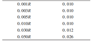
The estimation accuracy of pipe joint attitude Angle is directly related to the ultra-short baseline positioning accuracy, so the simulation verifies the relationship between the positioning accuracy and the attitude Angle estimation accuracy. The simulation steps are as follows: the accurate value of Euler Angle of immersed pipe in geodetic coordinate system is [5° 10° 15°], the positioning accuracy of the ultra-short baseline positioning system is changed, and the error of attitude Angle is obtained. Around the X axis attitude Angle error, for example ꎬ results are shown in table 1

Table 1 Relation between USBL positioning accuracy and Euler Angle about X axis
R in Table 1 is the oblique distance between the origin of the matrix coordinate system and the origin of the local coordinate system. It can be seen from Table 1 that when the positioning accuracy of the ultra-short baseline increases from 0.050R to 0.001R, the attitude Angle error of the recovery platform becomes smaller and smaller. Under the background of better hydrological environment, When the precision of the ultra-short baseline positioning system based on Notch filter is higher than 0. 010R, the attitude Angle error reaches 0. 010°, which can meet the engineering requirements of 2.2 sink tube surface
2.2 Number of transponders on submerged tube surface
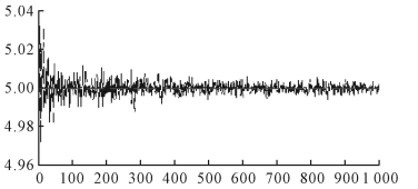
In theory, 3 transponders can determine the positioning surface of the sink tube, and the number of transponders, the more redundant information, the accuracy of parameter estimation has been improved, but the number of transponders is too much, it will increase the cost and computational complexity, in order to study the relationship between the number of transponders and attitude Angle estimation accuracy, the following simulation calculation: change the number of transponders, The position of each transponder is solved. With each additional transponder, the Euler Angle calculated last time is corrected by using the new redundant information, and the attitude Angle of the pipe joint plane (taking Euler Angle around the X-axis as an example) is solved, as shown in Figure 4

FIG. 4 Relation between the number of transponders installed on the pipe plane and the error of attitude Angle (around the X-axis)
Figure 4 shows ꎬ when transponder number increased from 3 to 1000 attitude Angle estimation precision also gradually improve, but the increase of the precision only in very small scale, highest do not exceed 0.020 °, is not in conformity with the engineering reality, international, and the simulation shows that when the positioning accuracy is higher than 0.010 R, When installed, the Angle estimate error of the three transponders is less than 0.010°.

Table 2 Relationship between the shape of the transponder and attitude Angle estimation (°)
It can be seen from Table 2 that the arrangement form of the transponder has no effect on the attitude estimation accuracy. This conclusion makes the installation of the transponder on the sink tube more convenient and can be flexibly selected according to the construction requirements to avoid the high noise area. At the same time, the transponder can be installed directly below the USBL array with high positioning accuracy, which helps to improve the accuracy of the pose algorithm.
3 Conclusion
Compared with a single traditional metering and control method for sinking pipe, this paper proposes a metering and control scheme for sinking pipe joint based on USBL positioning system. During the sinking stage of pipe joint, it can assist the pipe joint to be sunk to the area to be sunk more accurately (the rough measurement stage), and then complete the final docking and positioning process (the precise measurement stage) by combining the high-precision relative method. The advantages of this scheme are as follows:
1) The ultra-short baseline acoustic positioning system does not rely on auxiliary facilities on shore and gets rid of the limitation of offshore distance. At the same time, compared with traditional positioning methods, the acoustic positioning system still meets the construction accuracy in deep water. When combined with GPS system, the three-dimensional attitude parameters of submerged tube in geodetic coordinates can be displayed in real time. It can effectively assist the construction of sinking pipe in the far shore and deep water environment.
2) Low equipment cost, easy installation, high operation safety, ultra short baseline acoustic positioning system small size, low cost, only need to install 3 transponders on the surface of the submerged tube before operation, no need to install the measuring tower, installation process in the water, can reduce the construction personnel underwater operation times, the whole construction process of high efficiency, high safety, low complexity of operation.
Reference literature
[1] Wang Jiexian, Xu Chen, Lu Caiping. Real-time monitoring of sinking tube [J]. Journal of Surveying and Mapping, 2002, 31(Suppl. 1):70 ~ 72.
[2] Fan Dongming Lu Bo Xiang. Research on Some Problems in GPS Tunnel Plane Control Survey [J]. Journal of PLA College of Geodesy and Geodesy 1998(1):17 ~ 20.
[3] Suo Xuhong. Application of Combined Measurement and control Technology in the Installation of Extra-long submerged tube Tunnel in Haihai [J]. Highway, 2018(8):37 ~ 42.
[4] Zhang Yanchang and Huang Yongjun. Technology of installation, positioning and attitude monitoring of immersed tube in tunnel of Hong Kong-Zhuhai-Macao Bridge [J]. Oceanographic Surveying and Mapping, 2012, 32(5):25 ~ 28.
[5] Lu Huang, King of Su Lin, Ren Chaojun, et al. Application of Sonar method in real-time positioning measurement of pipe joint Sinking [J]. Modern Tunnel Technology, 2012, 49 (5): 132 ~ 136.
[6] Ren Chaojun, Lv Huangsulin, Wang et al. Analysis on the current situation of real-time positioning Measurement Technology of tube joint Sinking in immersed tube Tunnel [J]. Modern Tunnel Technology, 2012, 49 (1):44 ~ 49.


