


Design of intelligent liquid level control system based on ultrasonic wave
Liquid storage tank level control is a hot research issue, in order to realize the automatic control and detection of liquid storage tank level, in recent years, many scholars have carried out a lot of research, the main methods used are infrared method, ultrasonic method, reed tube sensor method, etc. In the infrared method detection, due to the application of infrared detector and sensor, the design in the system is more complex. Infrared sensor in use, due to environmental problems, easy to appear aging; The reed tube sensor method mainly belongs to the switch detection type, which can only detect the upper and lower limit of liquid level critically, and the detection accuracy is not high. Ultrasonic detection adopts the theory of light propagation, the detection is fast, the measurement accuracy is good, at the same time in the process of detection is not easy to be interfered by the power supply or the environment, so it has been widely used.
This paper intends to use single chip microcomputer as the control core, design key circuit module, digital display module, ultrasonic sensor module, integrated H bridge module, etc., complete a set of intelligent water level control system, detection error is less than 0.3%, stability time is less than 3 s.
1. Ultrasonic sensor and working principle
Ultrasonic module can provide non-contact distance test function of 2~400 cm, the test accuracy can reach up to 3 mm, the main module includes ultrasonic transmitter, receiver, and control circuit.
Basic working principle:
The ultrasonic module sends signals, and the signal is detected at the detection end. When the ultrasonic signal is detected, the time is recorded, where the distance is half the product of time and the propagation speed of light in the air.
Its circuit schematic diagram is shown in Figure 1.
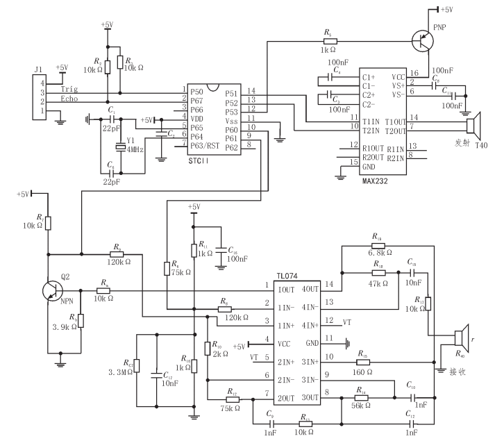
Figure 1 Schematic diagram of ultrasonic module
VCC is the power supply, the sensor is the 5V system, GND is the ground, pin TRIG is the trigger control signal input, ECHP is the echo signal output.
2 H bridge driving circuit and working principle
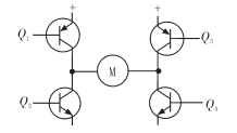
Figure shows a typical DC motor control circuit, which is driven by a H bridge composed of four triodes. H bridge motor drive circuit consists of four triodes and a motor. According to the design timing sequence, ensure that Q1 and Q4 or Q2 and Q3 are paired and switched on at the same time, so as to realize the current direction transformation in the motor M and realize the control of the motor running direction.
In the actual use of this circuit, when the current flow to Q1-M-Q4 is switched to Q2-M-Q3, there will be a moment when the first path is not completely closed, and the second branch will be automatically switched on, this situation is called through, when the through phenomenon occurs, the current does not flow through the motor M, and will produce a great current, It will bring great harm to the circuit. Therefore, it is necessary to improve the circuit and increase the "dead zone" time during direction switching. When one channel is completely closed, the switching can be carried out. The improved circuit diagram is shown in Figure 4. Four and gates and two not gates were added to the basic H bridge circuit.
Four are connected to the gate with the same "enable" pilot signal, which ensures that only one triode is on at any time on the same leg of the H bridge by providing a directional input. Thus eliminate the direct phenomenon.
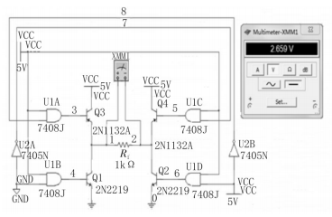
Figure 4 Improved H bridge drive circuit
3 SCM control system design
The system uses STC12 series or STC89C51 MCU system to design the control system. The specific design circuit diagram is shown in 5. The minimum system includes reset circuit, crystal oscillator circuit and power supply circuit.
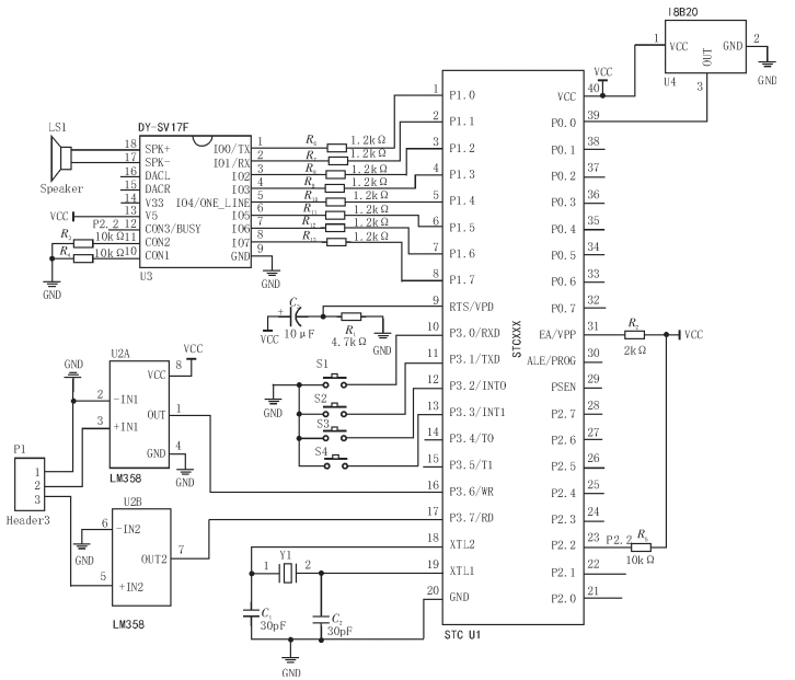
Figure 5 MCU control circuit diagram
4. Alarm circuit design
The alarm circuit is designed with active buzzer. The alarm circuit diagram is shown in Figure 6.
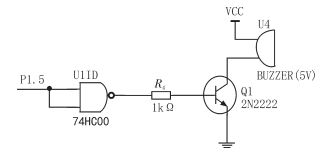
Figure 6 Alarm circuit
The buzzer is driven by 9012 triode, and its base is connected to RD end. When RD end is low level, the triode is switched on and the buzzer rings. Otherwise, shut it off. The positive terminal of the buzzer is connected to a 5V power supply, and the negative terminal is connected to the collector of the triode. The base of the transistor needs to connect the pin of the single chip microcomputer through the gate. When the pin is high level, the and gate output low level, the transistor stops conduction, buzzer power loss, no alarm; When the pin level is low, and non gate output high level, transistor conduction, buzzer in the current circuit to form an alarm alarm.
5 System software design
The software design adopts modular design idea, mainly includes key control program module, digital tube display module, timing interrupt program module, ultrasonic sensor control module, H bridge motor control module and so on.
6. Debugging and result analysis
According to the design of hardware and software, the system is debugged, and the debugging results are shown in Table.
According to the test results, the measurement stability time of the system is short, the test is completed within 3s, the measurement error is less than 0.3%, and the measurement accuracy is high. When the water level reaches the upper limit, the device will sound and light alarm, and stop the pump pumping; Similarly, when the water level is lower than the lowest level, the system will automatically start the pump to pump water, so as to realize the intelligent control of the water level, simple test, good human-computer interaction, and reach a higher level in similar projects.
References:
[1] ZHANG Yu, FAN Yanbin, HE Jinjin. Research on Tank Level Control System Based on MATLAB [J]. Industrial Control Computer, 2016,29 (11) : 59-60.
[2] Hou Guo-lian. Application of Yang Yu's Improved Constrained Predictive Control in Liquid Level Control System [J]. Computer Simulation, 2016,33 (10) : 381-385.
[3] ZHANG Wei, QI Kai Liang. Analysis and Design of Single-loop Liquid Level Control System Based on LabVIEW [J]. Foreign Electronic Measurement Technology, 2016,35 (10) : 50-53.
[4] Xu Zhangui. Simulation and PID Parameter Debugging of Single Tank Level Control System [J]. Modern Manufacturing Technology and Equipment, 2015 (5) : 132-134.
[5] Hu Jiangping. Innovative Design of Liquid Level Control System for Boiler Water Storage Tank [J]. Hunan Agricultural Machinery, 2014,41 (6) : 53-54.
[6] Wu Wanqiang, Wu Jie, Zeng Bifan, et al. Research on Pressure and Liquid Level Control System of Pressurizer in Nuclear Power Plant [J]. Thermal Power Generation, 2016,45 (10) : 115-119.
[7] Shi Ying, Chen Ke. Commissioning and Improvement of Evaporator Level Control System in Nuclear Power Plant [J]. Electronic Technology and Software Engineering, 2015 (4) : 132.
[8] Guo Yanping, Chen Hangxing. Design of Liquid Level Control System Based on LabVIEW [J]. Numerical Control Technology and Application, 2016 (3) :8.
[9] Qin Wenjie. Simulation and Calibration of Liquid Level Control System based on MATLAB [J]. Electronic Testing, 2016 (17) :70-72.
[10] Chang Jiandong, Hu Yuanxi, Zhao Wenxian, et al. Design and implementation of Liquid Level Control System Based on PID Parameter Self-tuning [J]. Modern Electronic Technology, 2016,39 (5) :153-160.
[11] Ding Fang, Li Yanfang, Fei Yulong. Application of Intelligent PID Algorithm in Liquid Level Control System [J]. Microcomputer Information, 2006 (16) :103⁃ 105.
[12] Li Xiaoli, Shi Longhui, Ding Dawei. Multi-model control Method of Water Tank Level System [J]. Control Theory & Applications, 2011 (3) :370⁃374.
[13] Lin Yi, Ye Xiaoling. Design and Simulation of Fuzzy Self-correcting PID Liquid Level Cascade Control System [J]. Laboratory Research and Exploration, 2010 (3) 17⁃ 20.
[14] Chang Jing, Fang Zeping, Yang Yi. Liquid level process control based on Virtual Instrument and PCI⁃6014 [J]. Instrument Technology and Sensor, 2013 (9) : 65⁃67.
[15] Zhou Nina. Water Tank Level Control based on Double Fuzzy Controller [J]. Modern Electronics Technique, 2011,34 (6) :140⁃141.
[16] Wu Xingchun, Yang Yanyun, Wu Ruiwu. Design of Automatic Pouring System based on Fuzzy PID Control Algorithm [J]. Foundry Technology, 2011 (12) : 1654⁃1657.