


Application of ultra short baseline positioning system in deep drag detection
0 Introduction
As the carrier of underwater exploration equipment, deep-sea towed exploration system (hereinafter referred to as deep-sea towed exploration system) has become an important tool for Marine scientific research, exploration and development or military activities because of its abundant equipment and high cost performance. In Marine geological survey, the deep-tow system is equipped with high-definition cameras, multi-beam, depth sounding side scan sonar and shallow formation profiler, etc., which is mainly used for submarine photography, deep-sea topography and near-sea bottom detection of formation characteristics. Deep-towed detection mainly involves navigation and positioning technology (including mother ship positioning, underwater towed body positioning and navigation, underwater target point coordinate conversion), detection technology (including all kinds of mission load sensor observation and data processing technology mounted on underwater towed body) and laying and recovery technology, etc. The schematic diagram of deep-towed detection operation is shown in Figure 1.
Navigation and positioning information is the key to deep-sea exploration. All measurement results need to be equipped with location information to be used effectively. As a platform carrying detection sensor, the accuracy of underwater position and attitude of the deep towing body directly affects the position accuracy of the final detection result. Therefore, determining the position information of underwater towed vehicle is a key problem to be solved in deep towing detection, and also a necessary condition for fine processing of data collected by deep towing system.
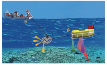
FIG. 1 Schematic diagram of deep drag probe operation
1. Navigation and positioning technology of deep towing system
1.1 Overview of underwater positioning technology
Underwater navigation and positioning methods generally include matching navigation (terrain/landform matching navigation, gravity matching navigation and geomagnetic matching navigation, etc.), underwater inertial navigation and positioning, dead reckoning and underwater acoustic navigation and positioning [7]. Matching navigation is a self-dominant navigation technology that makes use of the spatio-temporal distribution characteristics of Marine magnetic field, gravity field, ocean depth or seabed topography to make earth-earth physical navigation beacon and realize accurate positioning of underwater carrier. Due to the restrictions of navigation environment and limited navigation accuracy, it is not applicable to deep towing system. Inertial navigation system (INS) is usually not used alone in the application because of the obvious accumulation of navigation and positioning errors over time, but with the help of external auxiliary means to correct the cumulative errors in real time. The position error obtained by integral method of navigation position calculation based on Doppler log (DVL for short) will obviously drift with time. Deep towing system positioning using underwater acoustic navigation positioning, especially the ultra short baseline positioning system (USBL) because of its low cost, simple operation, no need to lay the seabed transponder, flexible installation, high ranging accuracy, has become the mainstream technical means of deep towing system positioning. In recent years, with the progress of science and technology, USBL transducer and inertial navigation system can be integrated installation, so it can be removed from the tedious calibration work, the operation is more convenient. Due to the complexity and randomness of Marine environment, for high-precision exploration tasks, only relying on a single positioning technology cannot meet the accuracy requirements of positioning and navigation, and multi-sensor integrated navigation and positioning technology is to combine more than two positioning systems to give full play to their advantages, so as to improve the accuracy and reliability of underwater positioning.
1.2 Deep-towed underwater positioning method
Due to the many technical means involved in underwater positioning, only some underwater positioning methods applicable to deep towing system are introduced in this paper.
1.2.1 Underwater acoustic positioning
Due to the particularity of seawater, the propagation energy of electromagnetic wave in seawater attenuates significantly, which limits the propagation distance of signals. Therefore, conventional technical means such as radio navigation and satellite navigation cannot realize the navigation and positioning of underwater targets. Acoustic wave attenuation in sea water, good propagation performance, propagation energy attenuation in sea water is not as obvious as electromagnetic wave, so acoustic signals are widely used in underwater communication and navigation and positioning.
The acoustic positioning system transducer is composed of several primitives (receiver transponder), and the lines between primitives are called baselines. Based on the length of baselines, there are three types: long baseline positioning system (LBL), short baseline positioning system (SBL), and ultra short baseline positioning system (USBL). The base line length of the LBL transducer is hundreds or even thousands of meters, which has the advantages of high positioning accuracy and wide operating range. However, the system composition is complex, the transducer array is large, and the deployment, calibration and recovery are time-consuming and energy consuming. Compared with LBL, SBL transducer array is much smaller, ranging from several meters to dozens of meters, which also has problems such as cumbersome installation and difficult calibration of hydrophones. With the development of the USBL technology, the baseline length of the USBL transducer is only a few centimeters to tens of centimeters, which makes it portable to install, easy to operate and even no need to check.
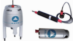
In addition to the acoustic unit, the conventional acoustic positioning system also needs a lot of external auxiliary equipment. The system is generally composed of the main control system on the mother ship, bottom positioning acoustic element array (transducer), underwater positioning beacon (transponder) and external equipment (GPS, compass, attitude sensor, pressure sensor and sound velocity profiler). Calibration is required prior to formal underwater positioning operations. In recent years, with the continuous progress of transducer integration technology and the innate advantages of short base line and small size of USBL transducer, its transducer and small inertial navigation system can be integrated installed. The relative offset between sensors has been internally calibrated and solidified in the internal program of the system before delivery. There is no installation and measurement error among various sensors, which ensures the high precision navigation and positioning of the system, thus avoiding tedious field calibration [18]. FIG. 2 shows the GAPS, a new ultra-short baseline underwater positioning system developed by IX-blue, a French company. The system is the first portable, plug-and-play, no-coordinate calibration ultra-short baseline positioning system in the world, which has attracted wide attention in recent years.
1.2.2 Dead reckoning and inertial navigation
The navigation position estimation method is based on Doppler effect, Doppler log (DVL for short) and other sensors to complete. The positioning principle is to calculate the position of the towed body relative to the mother ship by integrating the velocity information obtained by the DVL and combining with the information of the compass. In order to calculate the absolute geographical coordinates of the towed body, it is necessary to determine the initial position of the underwater towed body by a certain method with the help of the positioning system of the mother ship before the towed body enters the water. The initial position information and the measured velocity and azimuth information of the towed body are constantly superimposed to calculate. This method has the characteristics of high autonomy and strong concealment. Its data output is smooth and short time accuracy is high. Velocity errors measured by Doppler altimeter will not accumulate with time, but position errors obtained by integrating method will accumulate with time.
Inertial navigation system (INS) is divided into platform inertial navigation system (GINS) and strapdown inertial navigation system (SINS) according to the system structure, which can be used to measure the three-dimensional attitude, speed, position and other information of the carrier. GINS's inertial components are mounted on a physical platform, which, due to its large size and complex structure, is not conducive to use in subsea survey platforms such as deep towing. SINS is an evolution of GINS, a frameless system consisting of gyroscopes, accelerometers and microcomputers that is small, simple and easy to maintain. It is the main inertial navigation system used by subsea survey platforms. With the increase of time, the inertial navigation system will also show cumulative errors, so it is difficult to work independently for a long time. Various external auxiliary means should be used, such as DVL to provide speed reference information for fusion positioning. Figure 3 shows the integrated navigation system of INS and DVL.
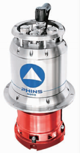
Figure 3 Combined INS& DVL system
2 USBL locating principles
2.1 USBL Locating Principles
Taking the GAPS ultra-short baselines as an example, the transducer acoustic array is composed of two orthogonal hydrophones and an emission transducer. By measuring the distance R between the transponder and the transducer, and recording the phase difference of the acoustic pulse to the transponder, the azimuth Angle θ between the transponder and the transducer is determined. The coordinate position of the transponder under the hull coordinate system can be obtained by means of rendezvous. The hull coordinate system is shown in Figure 4, where the origin O of the hull coordinate system is located at the center point of the transducer, T is the position of the transponder, the X and Y axes are in the horizontal plane, and the X axis points to the bow of the ship, the Y axis is perpendicular to the X axis to the starboard side, and the Z axis is perpendicular to the downward. The geographical location of the mother ship is determined by GPS, and the absolute geographical location of the transponder can be obtained by accurately measuring the offset from GPS to the origin O of the coordinate system.
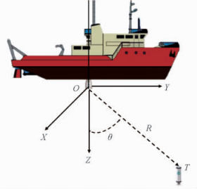
FIG. 4 Hull coordinate system
2.2 USBL positioning error Analysis
Assuming that the error sources affecting the USBL positioning accuracy are independent of each other, the positioning accuracy of the whole system can be defined as:
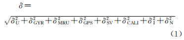
In Equation (1), δU is the measurement error of USBL itself, including ranging error and direction finding error, belonging to systematic error, and data update rate error; If the USBL is connected to the external sensor, it also includes the compass heading error δ2GYR, attitude sensor error δ2MRU, mother ship GPS positioning error δ2GPS, sound velocity error δ2 SV, and the above error is classified as the external sensor error. δ2CALI is the user installation calibration error, which is not considered when using the non-calibration USBL. δ2I is the error of different incident angles from the transducer to the transponder, which is closely related to the operating distance between the transducer and the transponder (including horizontal distance and vertical distance). δ2N is noise error and belongs to random error.
Course error will mainly affect the horizontal positioning accuracy of USBL. Attitude error affects both horizontal and vertical positioning accuracy of USBL. The mother ship GPS positioning error will be transmitted to the entire US-BL system, resulting in inaccurate geographical coordinates of the transponder measured. Sound velocity is very important for all acoustic detection means. The measurement error of sound velocity profile will affect the accuracy of sound line tracking, resulting in low positioning accuracy and even rough positioning error of USBL. During the USBL positioning work, the influence on the final positioning error of the USBL can be reduced by using high-precision compass, attitude sensor, GPS device and sound velocity profile measuring instrument. The data update rate error is mainly related to the measurement skew. When the distance between the transducer and the transponder increases, the data update rate of the USBL will decrease, resulting in that the USBL cannot provide positioning data within a certain period of time, resulting in the phenomenon of blank positioning data within a period of time. In the Marine working environment, USBL positioning errors and even gross errors caused by environmental noise are inevitable, which need to be solved by post-processing such as filtering of USBL positioning data.
2.3 Kalman filtering
Kalman filter can estimate the parameters in the system in real time, such as the continuously changing position, speed and other information. It is a linear optimization autoregressive data processing algorithm, which can process the observed data in real time and calculate the latest filtering value. Through the continuous prediction and correction recursive process, it provides a real-time optimal estimate value. State estimation is a key technology to obtain optimal navigation results from various valid observation data, and Kalman filtering is the basis of most state estimation algorithms in navigation systems [22].
Kalman filtering can not only use the current observation value, but also use the observation information input in the whole period to calculate. After obtaining the effective information, Kalman filter uses the prior knowledge of the deterministic and statistical properties of the system parameters as well as the observed quantity to obtain the optimal estimation. In real-time applications of navigation and positioning systems such as the USBL, the recursive method is more efficient because only new observations need to be processed in each iteration, while old observations can be discarded. On the basis of the initial estimate provided, Kalman filter updates the state estimate with the weighted average of the prior values and the new values obtained from the latest observation data through recursive operation.
In the case of uniform linear motion, considering the gross error observed frequently in underwater positioning, the mathematical model needed to be established, namely the equation of state and measurement equation, is linear of first order. The adaptive anti-error Kalman filtering algorithm mainly includes the following equations.
Observation equation and equation of state of adaptive weighted filtering after linearization:
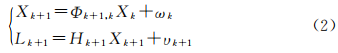
Where: Φk+1, k is the state transition matrix at the moment k+1;
xk is the n-dimensional state vector at time k, including position parameters and sound velocity correction parameters.
Lk+1 is the USBL observation equation; Hk+1 is the design matrix; ωk is state noise; υk is observed noise.
It is assumed that the expectations of ω and υ mathematics are 0 and are not correlated with each other, and their covariance matrices are Σk+1, k and Rk+1 respectively. The process of adaptive robust filtering is divided into status update and measurement update. The status update process is as follows:

Where: ^ Xk is the filtering value of n-dimensional state vector at time k, and its initial value is generally calculated from the observed value of a few epoch;
Xk+1, where k is the predicted value of the state vector after one step prediction.
3 Application of the USBL in deep drag positioning
The Gaps ultra-short baseline positioning system (FIG. 2) produced by IXblue in France is integrated with a high precision inertial navigation system, which does not require complex installation and calibration. This paper takes the system as an example to introduce the application of USBL in underwater positioning of deep tow detection. The deep towing operation, the mother ship at a speed of 3kn along a fixed course, deep towing system depth of about 600 m, USBL energy converter installed in the mother ship acoustic shaft, transponder installed on the towing body, using electric contact mode work. Figure 5 shows the position of mother ship (blue line) and towed body position (red line) displayed in real time in Delph Roadmap navigation software. In order to more intuitively display the relative position relationship between mother ship and towed body, part of the original data is intercepted and a 3D display diagram is drawn (Figure 6). It is not difficult to see from Figure 6 that the position of the mother ship is given by the high-precision satellite-station difference GPS, and its motion track is clear and continuous, as a straight line. The USBL can provide relatively stable location data in most of the time, but due to the influence of Marine environmental noise, some data may skip points.
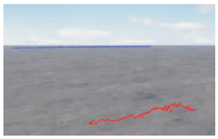
Figure 5 Real-time navigation interface
For underwater positioning of deep towing, the deep towing body and the mother ship are connected by photoelectric composite cable, and the mother ship tows the navigation operation, so the movement path of the towing body is regulated, the movement path is relatively smooth, and there will be no big mutation under normal circumstances. The original USBL data in the black box in Figure 6 showed obvious pulsation, and this part of data was selected for analysis. As shown in Figure 7, the position of the towed body showed obvious pulsation in both the plane direction and the vertical direction, especially in the vertical direction, the pulsation between adjacent positions could reach 5 ~ 10m.
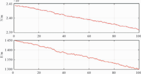
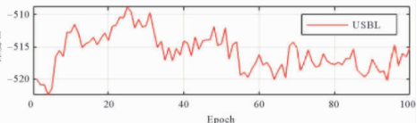
FIG. 7 Three-dimensional position of the towed body
4 Conclusion
The USBL is widely used in deep drag detection because of its flexibility and ease of operation. USBL positioning errors caused by Marine environmental noise may lead to a jump point in deep-towed underwater positioning data, resulting in discontinuous positioning track. Combined with the underwater motion characteristics of the deep towing body, the author constructs its stable dynamic model. The error can be effectively eliminated or smoothed by Kalman filter algorithm, which can obviously improve the final positioning result.
In this paper, only the USBL single technical means is used for deep-towed underwater positioning. Although the smooth positioning data is obtained through data post-processing, it is still far from enough for higher precision detection missions. As mentioned above, for high-precision detection tasks, USBL, DVL, INS and other multi-sensors are also needed for integrated navigation and positioning. Combined positioning technology can combine the two above positioning systems together to give full play to their advantages, so as to improve the accuracy and reliability of underwater positioning technology, which will become a new trend in the development of underwater positioning technology.