Design of high precision ultrasonic rangefinder based on FPGA
In order to improve the accuracy of ultrasonic measurement, a high precision ultrasonic rangefinder is designed by using FPGA technology. The hardware system platform based on SoP C is designed on high density programmable logic gate array (FPGA) by Quartus II software, and the software system of the measuring instrument is developed by nios II ED S development software. The high speed ultrasonic controller is designed by using the hardware resources in FPGA. The temperature sensor ds18b20 measures the ambient temperature and uses the temperature to correct the propagation speed of the ultrasonic wave. The test shows that the ultrasonic rangefinder designed by this scheme has a high range accuracy and has a certain practical and popularizing value.
0 Introduction
Ultrasonic rangefinder is a non-contact distance measuring tool using ultrasonic waves. Because ultrasonic has the advantages of good orientation, easy to use, low cost, strong anti-interference ability, so the ultrasonic rangefinder is used in industrial measurement, vehicle obstacle avoidance, safety warning, liquid level measurement and so on. The fields of mechanical internal damage detection, vehicle automatic navigation III and robot are widely used. However, at present, most of the ultrasonic rangefinders generally use MCS51 single chip microcomputer as the controller, and its measurement accuracy is limited by the timer clock frequency, which is not satisfactory.
In view of the above situation, this paper designs a set of embedded high-precision ultrasonic ranging system based on SoPCtgj using large-scale FPGA, adopts hardware and software co-design method, adopts custom IP core technology and temperature compensation technology. The test system has the characteristics of high reliability, high integration, fast response, high precision and low cost.
1 Hardware system design
In the hardware system, the rangefinder uses high density programmable logic gate array (FPGA) as the hardware design platform, and the system design block diagram is shown in Figure 1. The main devices are Nios lI processor, A Valon-m bus, JT AG controller, U APPA controller, EPCS controller, ultrasonic controller, LCD controller, EPCS4 memory, SD-R AM controller, SRAM memory, LDAC display, universal I/O port and H.C.SR04 ultrasonic transceiver module. To achieve complex control, a 32-bit Nios II processor is embedded in a programmable logic gate array (FPGA). N The ios II processor is a 32-bit soft-core processor provided by era. In the system design, the designer embedded the ios II soft-core CPU into the FPG A produced by A tera company for free according to the project requirements. The SD RAM controller controls the external SD RAM memory core chip for storing and storing data. The JTA GUA RT controller can download and debug programs online. The EPSC controller controls the EPSC memory chip. The EPSC memory chip is used to store the FP A configuration file. LCD controller Controls LCD display to display measurement data. The ultrasonic controller is a custom controller designed according to the electrical characteristics of the external ultrasonic transceiver module. The output pin of the controller is connected with the external ultrasonic transceiver module to control the ultrasonic transceiver module for ranging. Temperature has a great influence on the propagation speed of ultrasonic waves. The temperature compensation circuit is designed to improve the measurement accuracy. The system is connected to the DS18B20 digital temperature sensor via PIO.
2. Hardware system design
2.1 Design of ultrasonic controller
Ultrasonic controller is the core module of this system, and its design block diagram is shown in Figure 2. It is mainly composed of interface unit circuit, register group, frequency multiplier, counter and state unit. The interface unit circuit is used to connect the Valon-M bus to the ultrasonic controller. Because there is a decoder in the interface unit, all registers in the controller can be accessed by Nios II through the decoder. The function of the frequency multiplier is to double the frequency of the 50 MHZ system clock to 100 MHZ, thereby improving the measurement accuracy of the system. The coordination of each module in state machine control is realized by generating various timing signals. TR IG is the trigger signal of ultrasonic transceiver module; EC H is the input signal for ultrasonic reflection reception and judgment. s T is the counter start signal, and the high level counter starts counting; CLR is a counter clear signal. When the CLR is high, it clears the counter value to zero. H is the counter value, saving the control signal, H is the high power level, the current value of the counter is saved in the counter register. In the ultrasonic controller, three registers are also defined and defined.
2. Modular design of dual state machine
State machine module is the key module of ultrasonic controller, its function is to generate various timing control. Figure 3 is a state transition diagram of a state machine with five states: idle, Start, Count, data save, and counter Clear. The state machine is idle during the power-on process. Procedure Once the start instruction is written to the control register, the state machine enters the startup state. In the startup state, the startup register is cleared on one side of the state machine, and the ultrasonic ranging startup signal TR IG is generated on the other side, and the ultrasonic ranging module is started to generate ultrasonic waves. After completing these tasks, the state machine enters the counting state. In the counting state, the counter counts the 100 hz clock. When the ultrasonic transceiver module receives the ultrasonic wave reflected back by the obstacle, the energy value decreases, the counter stops counting, and the state machine enters the data saving state. In the data save state, the count data is stored in the count register. After the data is saved, the state machine enters the counter data zero state, at which point the value in the counter is cleared in preparation for the next count.
2.3 Hardware platform design
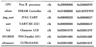
The SoP C hardware design of the ultrasonic rangefinder uses the SoP C B development tool of Altera. SoP C B builder is a powerful system development tool that makes it easy for embedded system designers to design systems on a chip based on ios II processors. In the graphical user interface of SoP CBuilder, designers can add functional modules from SoP CBuilder library to the system. SoPCBuilder also allows designers to add user-defined logical units to the SoPCBuilder library. The hardware system defined by the SoPC Builder development tool is shown in Table 2, where uhrasonc is the ultrasonic controller and the user-defined logical control unit.
2.4 Design of temperature compensation circuit
The propagation speed of ultrasound is highly affected by temperature. The propagation speed of ultrasonic wave at room temperature is about 340 m/s, but when the temperature changes, the propagation speed of ultrasonic wave will change, for example, when the temperature rises by 1 ° C, the propagation speed of ultrasonic wave will increase by 0.6 m/s, so the influence of temperature on the propagation speed of ultrasonic wave must be considered when using ultrasonic wave to measure distance.

Table 2 Definition of hardware system modules
In order to improve the measurement accuracy, the temperature compensation circuit is designed in this system. The temperature compensation circuit of this system mainly uses DS18B20 full digital temperature sensor to measure the ambient temperature, and then uses the following formula to compensate the ultrasonic propagation speed.

Where: is the propagation speed after ultrasonic compensation; T is the actual temperature.
3. System programming
In order to make the tester work properly, it is also necessary to design the control program of the system. The system program is developed by Nios lI EDS 8.0 integrated development environment of Ahera. Figure 4 is the algorithm flow chart of the system program. After the program is started, the main program of ios II initializes related devices of the system, such as LCD screen initialization, temperature sensor DS18B20 initialization, serial port initialization, and so on.
After system initialization, the ios lI soft-core CPU reads the temperature value of DS18B20 and obtains the temperature value of the current test environment. After reading the temperature, the start command is sent to the start register in the ultrasonic control system to start the ultrasonic ranging module to move the distance, and the working status of the controller is understood by reading the value of the status register. If the controller is busy, the controller will delay for a period of time to read the status information again. If the controller is known to be in the "idle" working state, the value in the count register is read and the propagation speed of the ultrasonic wave is corrected according to formula (1), and then the distance is calculated with the corrected propagation speed and the distance is displayed.
4. Check the test result
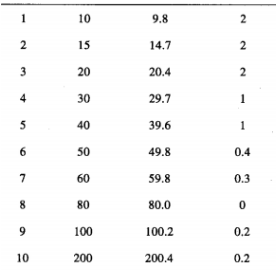
In order to further evaluate the accuracy of the ultrasonic rangefinder, a test prototype was designed by using high density FPGA and ultrasonic transceiver module, and its performance was tested. The FPG A adopts the EP 1C 6Q 240 C8 produced by Altera, and the ultrasonic transceiver module adopts HC. SR 04. Table 3 shows the test results of a group of test prototypes. It can be seen from the test results that when using this test to measure distance, except for the matching error error of measuring the short distance distance is 2%, the relative error of measuring the middle and long distance distance is kept within 1%. The measuring precision is high.

Table 3 Test results
5. Summary
Ultrasonic rangefinder is a non-contact distance measuring tool, which has many advantages. In this paper, a set of high precision ultrasonic distance measuring system based on Nios II is designed by using hardware and software co-design method and user defined IP core technology. The system has the advantages of high reliability, high integration, fast response, high precision and low cost.
Reference
[1] Wang Caijie, Zhang Daming, Zhang Meilu. Design of high precision ultrasonic ranging system based on FPGA "J]. Micromachines and Applications, 20 12, 31 (17) : 25 -- 27.
[2] Zhang Panfeng, Wang Yuping, Zhang Jian, et al. Design of ultrasonic rangefinder with temperature compensation [J]. Computer Measurement and Control, 20 12, 20 (6) : 17 17 -- 17 20.
[3] Zhang Quanyu, Su Baolin, Li Hualiang, et al. Design and implementation of ultrasonic wave ranging System based on FP GA [J]. Electronic Testing, 20 14(2 2) : 164. 165.
[4] ZHAO Haiming, Bu Yingxiong, Wang Jichan. Development of a high precision ultrasonic wave ranging system [JJ. Mining Research and Development, 20 06, 26 (3) : 62.65.
[5] Zhang Fen, Dong Haobin, Jiao Yanbin. Ultrasonic range measuring instrument based on C8 05 1F3 20 monolithic machine [J]. Instrument Technology and Sensors, 2009 (12) : 35 -- 37.
[6] Fan Hongxing, Zhang Xiaochao, Liu Lei, et al. Design of data collection system for CMOS linear array image sensor based on FPGA [J] _ Modern Electronics Technology, 2015, 38 (14) : 129 -- 1 32.
[7] Jia Yingtao, Gu Zhaoyu, Fu Qixiang, et al. Radar signal compression based on FPGA and DSP [J]_ Modern Electronic Technology, 20 15, 38 (17) : 13-16.
[8] Chen Pengming, Lu Zhenyang, Liu Jia, et al. Image and analog signal synchronous acquisition system based on FPGA [J]. Modern Electronic Technology, 20 15, 38 (19) : 7 9.8 2.
[9] Dai Junfeng, Mu Xin. Research on solution of Server controller based on SoPC [J]. Modern Electronic Technology, 2 015, 3 8(20) : 150. 15 3.
[1O] ZHAO Xiaoqiang, Zhao Lianyu. Temperature compensation in ultrasonic wave ranging system [J]. Combined machine bed and Automatic Processing Technology, 2008 (12) : 65-68.


