Integrated positioning system
The combined positioning System is composed of GPS(Global Position System), heading attitude sensor and ultra-short baseline positioning system. The conventional ultra-short baseline array is positioned by the phase method. In order to avoid phase ambiguity, the array spacing must be less than half a wavelength, so the positioning accuracy is not very high. The ultra-short baseline array in the combined positioning system is positioned by time delay method, and the array spacing can be much larger than half wavelength. During positioning, the combined positioning system floats on the surface of the ocean, and an upward-firing acoustic transmitter is installed with the target in the water. The pinger transmits a broadband signal and is received by the array. Maximum likelihood estimation is used. To obtain the delay between the transmitted signal and the received signal of the array. Large array spacing, wide signal bandwidth and accurate time delay estimation can greatly improve the positioning accuracy. The ultra-short baseline array has 4 elements. Four slants can be obtained from four delays. By using least square method and coordinate transformation, the longitude, latitude and depth of the target can be obtained. The results of location error simulation, delay estimation simulation and lake test are also given.
Combined positioning [1, 2] is the combination of satellite station GPS, heading attitude sensor and underwater acoustic ultra-short baseline positioning system for positioning, so as to obtain the accurate position of underwater targets.
The conventional positioning method of the ultra-short baseline array is based on the phase method. The position is determined by the phase difference of the output of the measuring array. The positioning accuracy is related to the phase consistency of the array. In order to avoid phase ambiguity, the array spacing must be less than half a wavelength, because the corresponding phase range is -2 to 2, so a small phase measurement error will make the positioning accuracy has a large decline.
This paper studies an accurate positioning method for ultra-short baseline array, which is based on the time delay method [3]. The relationship between positioning accuracy and element phase consistency is small. Since there is no phase ambiguity, the array spacing can be much larger than half wavelength. The time delay is estimated by maximum likelihood, so the positioning accuracy is very high.
When combined positioning is carried out, the positioned target is located at a certain location in seawater, as shown in Figure 1. There is a pinger above the target being located. The acoustic axis of the pinger points directly upward. On the surface of the sea, a floating body floated. The top of the floating body is a spherical top. Under the top of the ball is a cone. The large mouth of the cone table is combined with the top of the ball, and the small mouth of the cone table is connected with a long cylinder. The joint surface between the top of the ball and the conical table is just level with the sea level. The antenna of the satellite station GPS is installed in the floating body, and the equivalent center of the antenna is located in the center of the circular joint surface. And the height is exactly the level of the ocean. At the equivalent central position of the satellite station GPS antenna, the cross section of the floating body has a larger diameter to avoid the shielding of the satellite station GPS antenna by seawater. There is a high-precision heading attitude sensor and an ultra-short base line array at the bottom of the long cylinder of the floating body. The high-precision heading attitude sensor can give accurate heading Angle, pitch Angle and roll Angle.
The precise position of the pinger can be determined by the ultra-short baseline array, the heading attitude sensor and the satellite-station GPS. Since the pinger is mounted with the target being located, the longitude, latitude and depth of the target being located can be precisely determined.
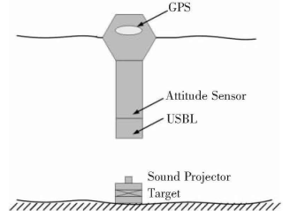
Figure 1 Combined positioning system
1 coordinate system
The position of the equivalent center of a satellite-station GPS antenna, namely its longitude, latitude and altitude, can be precisely determined by satellite-station GPS.
The equivalent center of the satellite station GPS antenna is set as the origin On of the navigation coordinate system, and the three axes Xn, Yn and n of the navigation coordinate system point north, east and vertical downward, respectively.
The origin of the carrier coordinate system Ob coincides with the origin of the navigation coordinate system On. The three axes of the carrier coordinate system, Xb, Yb and b, point to the front, right and vertical downward of the carrier respectively.
The navigation coordinate system first rotates an Angle about the z axis, then the corresponding direction cosine matrix is:

Then, if one Angle is rotated about the Y-axis after rotation, the corresponding direction cosine matrix is:

Finally, if one Angle is rotated about the X-axis after the second rotation, the corresponding direction cosine matrix is:

2 Ultra-short baseline array
The ultra-short base matrix has four elements. Their positions in the ultra-short baseline coordinate system can be expressed as:
[+ d, 0, 0] matrix 1
[-d, 0, 0] matrix 2
[0, +d, 0] matrix 3
[0,-d,0] matrix 4
In this way, the slant distances r1, r2, r3, and r4 from the pinger to the four arrays should satisfy:
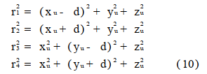
The corresponding sending and receiving delays are as follows:

Where c is the sound velocity of seawater.
3 Time delay method ultra-short baseline positioning principle
The so-called time delay method of ultra-short baseline positioning is a method of positioning by using ultra-short baseline array and relying on measuring the time difference between multiple transceivers.
If the four measured time differences between sending and receiving are:

ei is the random error of measuring time. Then the measured values of the 4 oblique distances should be:

With the measured values of these 4 oblique distances, the measured values of the position of the acoustic transmitter in the ultra-short baseline coordinate system can be obtained by using the least square method [4, 5] :

It can be seen from equation (10) that the measured values of the 4 oblique distances should meet:
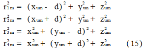
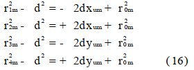
The above formula is not difficult to evolve into:
4. Simulation of positioning error
The main sources of positioning error are: positioning error of satellite-station GPS, Angle measurement error of heading attitude sensor, sound velocity measurement error and transmission delay measurement error. The positioning error of the satellite station GPS is in the order of centimeters, the angular error of the heading and attitude sensor is less than %, and the measurement error of the sound velocity is less than %, which can be ignored. The positioning error is mainly caused by the self-measuring error. If the position of the acoustic transmitter in the navigation coordinate system is [0m;0m; 100m], L= 5 m, d = 0 375 m, course Angle, pitch Angle and roll Angle are 0, and the standard deviation of measurement time is 0.5 s, then the standard deviation of the position of the acoustic transmitter in the navigation coordinates xn, yn and zn are 0 135 m, 0 135 m and 0 000 4m, respectively. The measured position is shown in Figure 2.
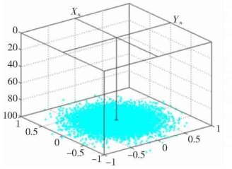
Figure 2 Target position obtained by simulation
5 Simulation of delay maximum likelihood estimation
In the simulation, the transmitting signal is a wideband FM signal, and the correlation system and differential correlation system [6] are adopted to achieve the maximum likelihood estimation of the delay. During the simulation of delay maximum likelihood estimation, the system parameters are shown in Table 1.
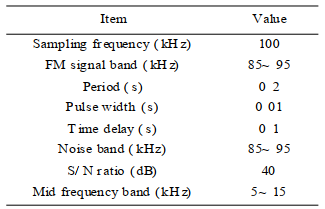
Table 1 System parameters
The simulation results are shown in Figure 3. The correlation output is shown by the solid line in the figure above, and the differential correlation output is shown by the dotted line in the Figure above. The following figure shows the details of the correlation output and the differential correlation output, as shown in Figure 3, where the correlation output reaches the maximum while the differential correlation output just crosses zero.
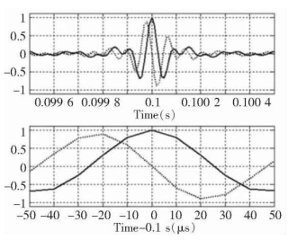
Figure 3: Correlation output and differential correlation output when = 0 1 s
If the relative delay between the two signals is changed to 01s+ 1s, the corresponding simulation result is shown in Figure 4, and the dotted line crossing position in the bottom of Figure 4 is just 1s to the left. Obviously, the measurement error should be less than 05s.
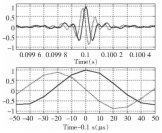
Figure 4: Correlation output and differential phase correlation output when = 0 1 s+ 1 s
When the correlation system and differential correlation system are used for delay estimation, there should be no phase distortion between the two signals. In practical problems, there is always phase distortion between the two signals. At this time, the common method of radar signal parameter estimation can only be adopted, that is, the time delay estimation can be performed by using the module of the complex correlation function and its difference [7].
6 Lake test results of combined positioning system
NavCom's SF-2050M GPS is selected for the satellite station type of the combined positioning system, and the water level position positioning accuracy is < 15 cm. The heading and attitude sensor adopts IXSEA's PHINS fiber optic gyroscope [8~ 10], heading accuracy :0 01(with GPS assistance), pitch and roll accuracy (RMS) :0 01. The frequency band of linear frequency modulation is 85~ 95 kH z, the pulse width is 64 ms, the receiving bandwidth is 85~ 95 kH z, and the sampling frequency is 80 kH z. The modulus of complex correlation function and its difference are used to estimate the delay.
The depth of the suspended sound source is 40 m. In order to provide the horizontal reference position of the suspended sound source, another satellite station GPS is floating on the water surface directly above the suspended sound source. This satellite-type GPS has a soft connection to the drop source. When the surface wind speed and underwater velocity are equal to 0, the satellite GPS can provide the accurate position of the dropped sound source. When the surface wind speed or underwater velocity is not equal to 0, there is a deviation between the reference position of the suspended sound source provided by the satellite station GPS and the actual position of the suspended sound source.
During the lake test, there are three horizontal distances between the combined positioning system and the suspended sound source: 5 m, 12 5 m and 18 7 m. Before the experiment, the time synchronization of the two systems was carried out. The position indication signal is emitted by the suspended sound source, and the position of the suspended sound source is calculated by combining the positioning system and compared with the reference position of the suspended sound source.
In the above three different positions, the calibration difference of X square direction (due north direction) and Y square direction (due East direction) is shown in Table 2.
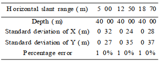
Table 2 Standard deviations of X and Y
When the horizontal slope distance is 5 m, the distribution of lake test data is shown in Figure 5. The data near the origin in the figure is the horizontal reference position measured by the satellite station GPS above the suspended sound source, and the data in the other area is the horizontal position measured by the combined positioning system. The data distribution area when the horizontal distance is 5 and coincides with the data distribution area when the horizontal distance is 5.
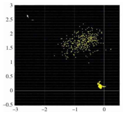
FIG. 5 Distribution of lake test data at a horizontal distance of 5 meters
There are two problems in the lake test: 1) Because the surface wind speed and underwater velocity are not equal to 0, there is a certain deviation between the measured water level position and the horizontal reference position. 2) During the lake test, the Angle of pitch and roll can change up to 8 in 1 s, if 0 8 is not compensated, it will cause a deviation of 0 56 m. This is because the center of gravity of the floating body in the combined positioning system is too close to the center of buoyancy. When the combined positioning system is affected by the wind and waves on the water surface, the combined positioning system cannot keep straight. The Angle of pitch and roll changes widely and fluctuates quickly, so that the attitude of the ultra-short baseline array cannot be compensated in time, thus increasing the data dispersion. If the center of gravity of the floating body in the combined positioning system is moved down, the change of attitude is reduced, and the dispersion of data is expected to be greatly reduced.
7 Closing remarks
When the target is located in the range of 45 of the normal line of the ultra-short baseline, the positioning method introduced in this paper is expected to keep the positioning error within 0 3% slant distance at high SNR. Because the broadband signal is used, it has a strong ability to resist multi-path interference and anti-noise. Because the ultra-short baseline array has 4 elements, there is redundancy. Redundancy can be used for data quality management (DQA) and Data quality control (DQC). In addition, when the floating body of the combined positioning system can still be positioned when only 3 oblique distances are measured, its center of gravity must be much lower than the center of buoyancy to maintain the stability of the floating body attitude and reduce the dispersion of data.
References:
[ 1 ] Morgado M, Oliveira P, Silvestr e C. Exper i menta l evaluat ion of a U SBL under wat er positioning system. ELMAR 2010 Proceedings,2010, 485 to 488.
[ 2 ] Morgado M, Oliveira P, Silvestre C. Designand evaluation of an integrated USBL/ INS system for AUVs. IEEE Int ernational Confer enceon Robotic and Automat ion, 2010: 4264~ 4269.
[ 3 ] Binham B, Blair B, Mindell D. On the design of dir ect sequence spread spectrum signaling for range est imation. Ocean, 2007: 1~ 7.
[ 4 ] Dr aper N R, Smith H . Applied regression analysis, 3rd Edition. New York: John Wiley and Sons, 1998.
[ 5 ] Bevington P R, Robinson D K. Data reduction and er ror analysis for the physical sciences. 2nd Edition. B


