Subminiature pressure sensor based on piezoresistive effect of monocrystalline silicon
There are many companies producing piezoresistive pressure sensors and transmitters abroad. Early adopters include ENTRAN and Endev-Co of the United States. In particular, ENDEVCO Company has developed a variety of silicon double island pressure sensors with micromachining technology, and has been widely used in aviation and aerospace dynamic pressure test. At present, the representative companies of the production of "stainless steel diaphragm isolation type" piezoresistive pressure sensors are: ICSensors, NOVA, SENSYM and KELLER of Switzerland. Their typical product performance is the world's leading level. So far, domestic pressure sensor only accounts for about 20% of the demand in China, and many foreign companies led by the United States in the development of the "stainless steel diaphragm isolation type" piezoresistive pressure sensor, then began to vigorously explore the Chinese market, accounting for 70% to 80% of the domestic demand. The main domestic manufacturers (companies) engaged in the production of civilian piezoresistive pressure sensors are Baoji Mack Company, Bengbu Kulit Company and Shenyang Instrument Technology Research Institute. Now the existing "stainless steel diaphragm isolation type" piezoresistive pressure sensor has single appearance size, low technical indicators, poor temperature stability, which can only be used for industrial or civil use. And low production, incomplete varieties, has not yet formed a series, standardization, can not meet the domestic market demand.
The sensor is made of MEMS technology, semiconductor micromachining technology, electrostatic packaging technology and vacuum oiling technology. The pressure sensing diaphragm is 316 stainless steel, so that the measured medium and the sensitive element isolation, strong structure, stable performance, has a wide range of media compatibility and other advantages. The output signal is converted into a standard voltage signal (0 ~ 5) V by an amplifying circuit. The sensor also has high precision, good stability, small size anti-vibration, impact and other characteristics, can be widely used in petroleum, metallurgy, chemical industry, aviation, aerospace, weapons equipment and other fields of pressure measurement and control.
1 Working Principle
The resistivity of monocrystalline silicon material changes when it is subjected to force, and the resistivity changes differently in different crystal direction. The sensing element of the sensor is made of the principle of piezoresistive effect of monocrystalline silicon. An elastic diaphragm with the thickness corresponding to the range of the sensor is formed on the monocrystalline silicon. Four strain resistors are formed on the elastic diaphragm by the microgalvanic process to form a Wheatstone bridge. When the pressure is applied, the elastic diaphragm will deform, forming positive and negative strain zones, and the resistivity of the material will change accordingly. Through reasonable design, when the monocrystalline silicon sheet is subjected to pressure, the resistance values of two resistors on one arm of the bridge increase, and the resistance values of two resistors on the other arm decrease. In this way, under a certain power supply excitation, the output end of the bridge will output a voltage signal proportional to the measured pressure.
2 Scheme Design
According to the technical specifications and size requirements of the sensor, the scheme adopts silicon piezoresistive double island structure, sensor sensitive core with isolation diaphragm, and attached with signal amplifying and conditioning circuit to realize the function of the pressure sensor.
2.I sensitive core design
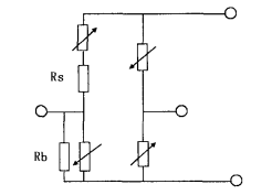
The double-island silicon cup is a thin film made of monocrystalline silicon material with two hard islands in the center, and then diffuses four form-sensitive resistors at specific positions on it, and forms a Wheatstone bridge through metal interconnection. When the elastic diaphragm is subjected to uniform fluid pressure, the two resistors of one arm of the bridge increase and the two resistors of the other arm decrease. In the case of constant current supply, the output of the bridge is proportional to the pressure on the diaphragm.

Figure 1 Equivalent circuit
For a traditional C-type silicon cup structure, the two pairs of force-sensitive resistors are usually longitudinal tension or longitudinal compression, their nonlinear values are smaller than transverse tension or compression, but the same sign, so that the non-linear increase. For the rectangular double-island silicon film structure, the two pairs of force sensitive resistors are located in the central groove between the two islands and the edge groove between the island and the frame. The stress analysis of the double-island structure shows that the stress is mainly transverse stress because the groove width is much smaller than the groove length. When its front face is pressed, the upper surface of the edge groove where the P-type resistance R is located is subjected to tensile stress, while the upper surface of the central groove where R is located is subjected to compressive stress. In this case, the nonlinear symbols of R and R are opposite but the values are similar, so the nonlinear compensation can be realized.
According to the above analysis, two of the four strain resistors are designed in the central groove of the diaphragm, and two are designed respectively in the edge groove on both sides, so that one pair of them can feel the compressive stress and the other pair can feel the tensile stress, so as to obtain the maximum sensitivity and carry out nonlinear compensation. In the design, in order to improve the performance of the sensor, the length and width of the four resistors should be equal; Equal stress; The doping concentration is equal. This can reduce the zero temperature drift of the sensor.
The silicon cup and the glass base are sealed together in vacuum by electrostatic sealing method, so that a vacuum reference pressure chamber is formed inside the silicon cup. Stainless steel corrugated diaphragm is used for isolation packaging, and the cavity of the chip and the stainless steel diaphragm is filled with silicon oil, so as to realize the pressure transfer from the corrugated diaphragm to the silicon oil and the chip.
2.2 Temperature Compensation
Diffused silicon piezoresistive sensor has been widely used for its high sensitivity output, good dynamic response, high measurement accuracy, good stability, easy miniaturization and mass production, but the diffused silicon piezoresistive sensor is affected by the ambient temperature, and will produce a large zero and sensitivity drift, which greatly limits its application. So it is very important to take appropriate temperature compensation measures. The following measures are mainly taken to reduce the temperature drift:
(I) In the diffusion process of the production of the sensitive element, the ion injection method is used for doping, so as to minimize the differences in the resistance values and temperature coefficients of the four sensitive resistors;
(2) Appropriately increase the doping concentration of the diffusion resistance strip, and slightly sacrifice the sensitivity to reduce the temperature coefficient of the diffusion resistance and sensitivity temperature coefficient;
(3) Select appropriate glass base material with expansion coefficient similar to silicon material to reduce the thermal stress generated by the connection with the glass base;
(4) The connection between the diffused silicon wafer and the glass base adopts the electrostatic sealing process. This process can not only connect the silicon wafer and the glass reliably, but also eliminate the aging and hysteretic effects caused by the addition of materials along with the change of temperature due to the joint of the two without any added materials.
(5) The temperature compensation method of series and parallel resistance of external circuit is used to compensate the zero point and sensitivity of the sensor. The compensation circuit is shown in Figure 3.
The zero output of each sensitive core at different temperatures is measured. According to the specific value of the zero temperature drift of each sensitive core, different series and parallel resistors R and R are selected to reduce the thermal zero drift of the sensor to the value required by the index.

Figure 3. Sensor temperature supplementary circuit diagram
2.3 Design of signal conditioning circuit
Due to the requirement that the sensor should have a DC voltage output of (0 ~ 5)V, and the output of the sensitive core is only tens of millivolts, so it is necessary to amplify the output signal of the sensitive core. Signal processing circuit actually includes two aspects of the design, one is the design of the sensitive core power supply circuit (constant current source design), the other is the design of the amplifier circuit.
2.3.1 Constant current source Design
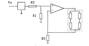
Because the resistance R of the bridge arm is sensitive to temperature, the resistance value increases with the increase of temperature, while the sensitivity decreases with the increase of temperature, so the constant current source can compensate the temperature drift. The sensor adopts a constant current source in the form of voltage to current conversion. The Wheatstone bridge of the sensor sensor is placed in the feedback loop of the integrated operational amplifier, as shown in Figure 4. z is a high precision reference voltage source, R and R are partial voltage resistors, and R is used to adjust the size of the current.

FIG. 4 Schematic diagram of constant current source circuit
2.3.2 Amplifier circuit design
The circuit design adopts the signal processing circuit as shown in Figure 5.
Loop 5 sensor signal processing circuit diagram
In the design process of printed circuit board, in order to reduce the radiation emission of electronic circuit, it is necessary to reduce the ring area of differential film radiation caused by the current flowing through the circuit wire, especially the ring area of digital circuit. Since the thin and long back wire presents high inductance, its impedance increases with frequency. To avoid causing impedance coupling, use copper foil plates and the widest possible trace. Power wiring, considering the safety conditions, the power line is as close to the ground as possible to reduce the ring area of the differential film radiation, also helps to reduce the circuit interference. In addition, to avoid the printed circuit version of the wire discontinuity, trace width does not change, wire does not suddenly corner.
3 Test results and analysis
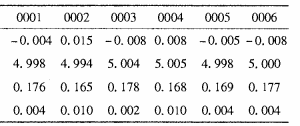
According to the conditions and methods stipulated by the corresponding subminiature pressure sensor, the performance test of the product after process examination is carried out, and all the indexes of the product meet the requirements. The test results of main performance indexes are shown in Table 1.

Table 1 Main performance index test results
The sensor was produced in two batches for performance testing, three in each batch, making a total of six. Through the whole process test, the qualified rate reaches 100%. The test results show that the product design is reasonable, the process design is feasible, has the operability, can meet the requirements of mass production.
4 Closing Remarks
The ultra-small pressure sensor (hereinafter referred to as the sensor) is based on the piezoresistive effect principle of single crystal silicon, and is manufactured by advanced semiconductor plane technology, micromachining technology, temperature compensation and solid-state integration technology. Products in the process of production after strict process inspection and environmental performance test. From the perspective of social benefit, the application research of the sensor lays a good foundation for the improvement of Chinese weaponization. According to the special points of the sensor, the sensor can be popularized in many application fields, and become a replacement product in the field of aviation and aerospace pressure measurement. And the sensor is small in size and light in weight, suitable for the field with special requirements on volume and weight.
Reference literature
[1] Liu Enke, Zhu Bingsi, Luo Jinsheng, Ed. Physics of half conductors [M]. National Defense Shangye Press, 1989.
[2] Zha f Lin, Li Wei, Yang Canjun, et al. Research Status and Prospect of Power-MEMs [J]. Machine Tool & Hydraulics, 2004, 9:5 -- 54.
[3] Liu Xiaowei, Deng Qin. MEMS Micro Power Supply Technology [J]. Sensor Technology, 2003,22 (7) : 771-R0


